Difference between revisions of "Time Frequency Resolution In BESA"
(Created page with "== Introduction == The time-frequency resolution of the complex demodulation used in BESA depends on the user-settings for “Frequency and Time Sampling” in the “Coheren...") |
|||
| Line 9: | Line 9: | ||
| − | [[File: | + | [[File: Time_Frequency_Resolution.png]] |
Revision as of 13:47, 7 March 2016
Introduction
The time-frequency resolution of the complex demodulation used in BESA depends on the user-settings for “Frequency and Time Sampling” in the “Coherence” tab of the ERP dialog box. The following table lists the 50% power and amplitude drops, respectively, as a function of the time-frequency sampling setting. Frequencies are given relative to the center frequency of a sharp frequency oscillation, latencies are given to the latency of a sharp time event. For example, with a time-frequency setting of 1.0 Hz, 50 ms, a sine wave with sharp frequency f will be smoothed to a time-frequency signal that has a full power width at half maximum of 2×1.42 Hz. In other words, at frequencies f ± 1.42 Hz, the displayed power in the time-frequency plot is half of the displayed power at frequency f. A sharp time-event, (e.g. a sharp spike in the time-domain) will be smoothed to a time-frequency signal of 2×78.8 ms full power width at half maximum.
Table
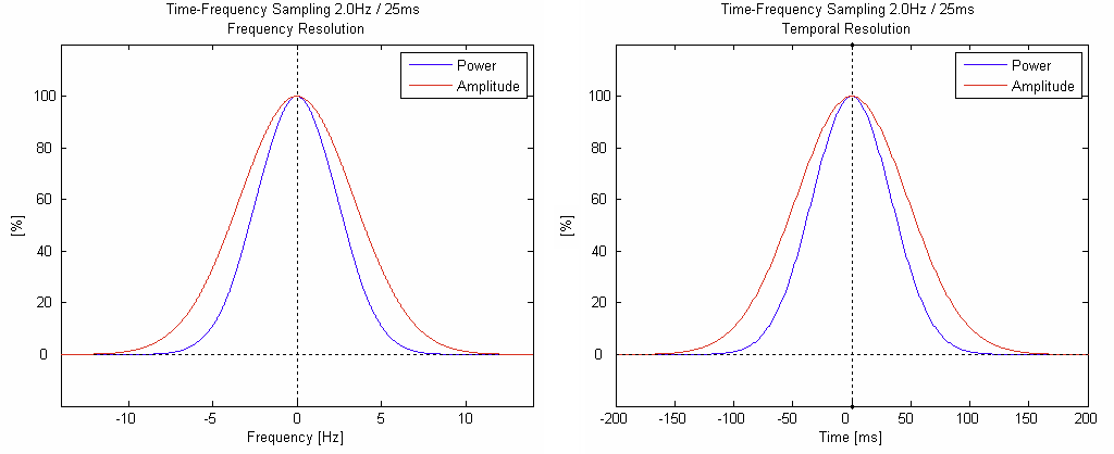
The following two plots show the frequency blurring (left) and the temporal blurring (right) for a time-frequency sampling of 2.0 Hz / 25 ms. When applying a denser frequency sampling, the frequency resolution will increase, and the time resolution will decrease proportionally (i.e. the x-axis scaling will change proportionally).
