Difference between revisions of "Recommended Electrode Configurations"
| Line 50: | Line 50: | ||
F11, FT9, A1, TP9, P11, F12, FT10, A2, TP10, P12 | F11, FT9, A1, TP9, P11, F12, FT10, A2, TP10, P12 | ||
EEG43 represents the widest coverage with relatively even spacing. | EEG43 represents the widest coverage with relatively even spacing. | ||
| + | |||
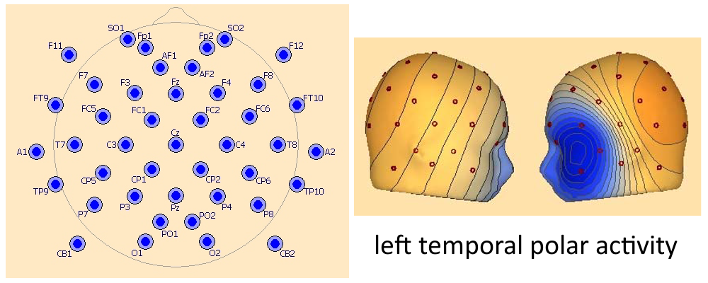
| + | [[File:LeftTemporalPolar.png|none|Figure 3 EEG43 – Inferior chain with 5 electrodes including A1 / A2]] | ||
| + | |||
===EEG64-256=== | ===EEG64-256=== | ||
Revision as of 13:16, 12 May 2016
| Module information | |
| Modules | BESA Research Basic or higher |
| Version | 5.2 or higher |
Contents
- 1 General considerations
- 2 EEG25 - Minimum 10-20 configuration including inferior electrodes
- 3 EEG33 - Additional 10-10 electrodes within the major squares
- 4 EEG35 - Additional supraorbital electrodes for better EOG separation
- 5 EEG37 - Wider inferior coverage at interlaced 20% distances
- 6 EEG41 – Improved frontal and occipital coverage
- 7 EEG43 – Inferior chain with 5 electrodes including A1 / A2
- 8 EEG64-256
General considerations
There are three important aspects for source analysis and source montages:
1) Electrodes should have equal spacing.
2) A row of inferior temporal electrodes on both sides is important to cover the lower head sufficiently, e.g. F11 (F9), A1, P11 (P9). The lower sites (F11, P11) at a 20% distance are preferable to sites at a 10% distance (F9, P9) from the standard row F7, T7, P7 (same applies to other side).
3) Electrodes should be symmetric between both hemispheres with a midline reference or an implicit reference (e.g. F3+F4). A recommended standard with 33 electrodes adds a midline reference Pz, and F11, A1, P11, FC1, FC5, CP1, CP5 and their homologues over the right hemisphere to the 19 electrodes of the 10-20 system (Fpz, Oz not included). For more details see BESA help chapter on Electrodes. When using caps with more electrodes (64 or 128) inferior electrode and equal spacing are similarly important.
In the following montage EEGxx the number xx indicates the number of electrodes.
EEG25 - Minimum 10-20 configuration including inferior electrodes
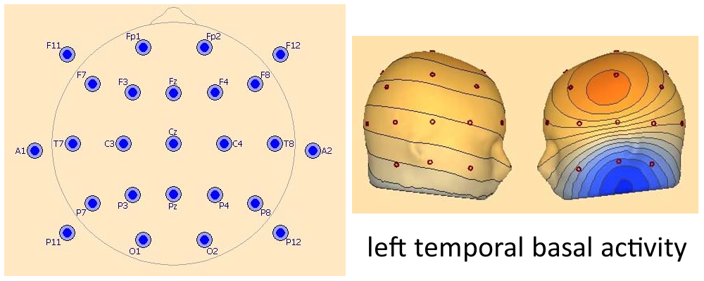
This covers the 19 standard 10-20 electrodes: Fp1, Fp2, F7, F3, Fz, F4, F8 .... plus 6 inferior electrodes on both sides: F11, A1, P11, F12, A2, P12 with a recommended continuation of the 20% distances, i.e. use F11 instead of F9, P11 instead of P9, A1 instead of T9 to have a wider coverage of the inferior head. A1 / A2 may be replaced by T9 / T10 (or FT9 / FT10) for convenience and comfort.
EEG33 - Additional 10-10 electrodes within the major squares
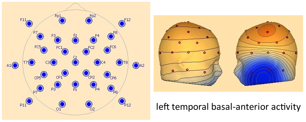
To the above electrodes add the following 8 intermediate electrodes: FC5, FC1, FC2, FC6, CP5, CP1, CP2, CP6
EEG35 - Additional supraorbital electrodes for better EOG separation
SO1, SO2
EEG37 - Wider inferior coverage at interlaced 20% distances
Continue 20% down from F7, FC5, CP5, P7 etc. and use the following 8 inferior electrodes instead of 6: F11, FT9, TP9, P11, F12, FT10, TP10, P12
EEG41 – Improved frontal and occipital coverage
Additional electrodes halfway between Fz and Fp1 / FP2 and Pz and O1 / O2: AF1, AF2, PO1, PO2
EEG43 – Inferior chain with 5 electrodes including A1 / A2
F11, FT9, A1, TP9, P11, F12, FT10, A2, TP10, P12 EEG43 represents the widest coverage with relatively even spacing.
EEG64-256
With 64 or more channel caps it is similarly recommended to use a sufficient number of inferior electreodes all around the head. At least 4 inferior temporal electrodes on each side and additional electrodes above or below the eyes (outside of the cap) are suggested. We can recommend EGI Geodesic nets (64, 128, 256) and the equidistant EasyCap 61 with additional 3 electodes for free placement around the eyes, or EasyCap 128 with nearly equidistant electrodes.
EGI: Dense Array EEG
EasyCap: EEG Recording Caps


