How to deal with TMS artifact in BESA Research
| Module information | |
| Modules | BESA Research Standard or higher |
| Version | 6.1 or higher |
Contents
Before you start
This article guides you through the reduction of the artifact introduced by Transcranial Magnetic Stimulation (TMS). Here, it is assumed that you already posses a good knowledge about BESA Research, ERP analysis, and source analysis. If you have any doubts it is strongly advised to follow the BESA Tutorial chapters indicated in this article or to consult with the BESA support team.
Make sure that your EEG recording system is suitable for recording during TMS stimulation. That means the maximum input range is high enough for the amplifier not to get saturated (the incoming signal induced by TMS artifact will not be higher than the input range). Most of the modern TMS-EEG systems have an automatic TMS pulse artifact suppression system that prevents the EEG amplifier from recording the signal during the stimulation. BESA strongly advises using this option since it makes the analysis much easier and assures that the amplifier is not saturated (contact Brainbox for details). Please note that neither BESA nor any other software can "fix" data if the amplifier goes into saturation.
During TMS stimulation at least three types of artifacts can be distinguished:
TMS pulse artifact
This artifact is induced directly in EEG electrodes and wires by the induced magnetic field due to Maxwell’s second law. It is a high-amplitude, short-latency artifact. Because the best way to handle this artifact is to suppress it during the recording we will not focus on it here.
TMS decay artifact (muscle)
Immediately after the TMS stimulation, a head muscle response is invoked (also due to Maxwell's second law). It has a large amplitude and it can last long enough to overlap with a cortical response. It has a characteristic shape resembling a free induction decay curve. This artifact is of major importance and it will be shown below how to reduce its influence.
Similar to any other strong sensory stimulation, eye blinks can occur as the derivate response. This type of artifact can be easily solved in BESA Research using traditional artifact reduction approaches. Please check BESA Tutorial chapter 2A for a basic or 10 for an advanced approach.
Example
The presented data was obtained by Brainbox. It was a 30 channel EEG recording of a male adult. During the experiment, TMS stimulation was performed with 120% rMT over the left motor cortex.
Pipeline
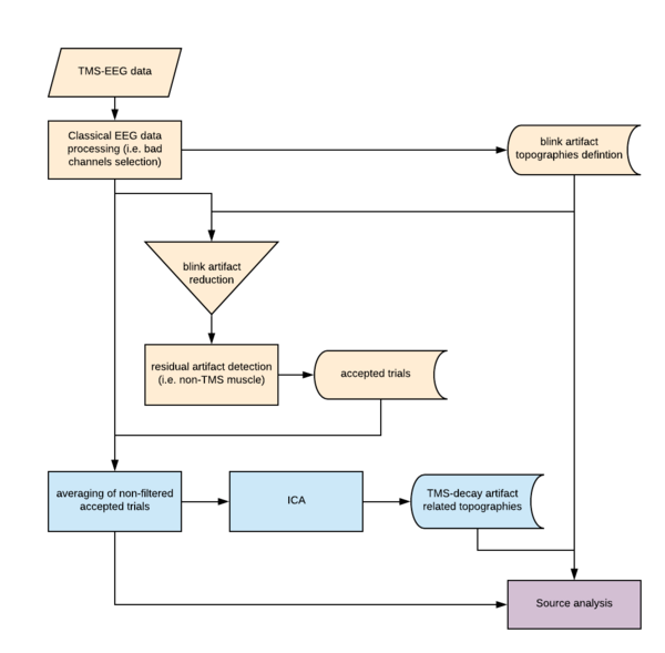
In the scheme below the TMS-EEG data handling pipeline is shown. Each part of the analysis is color-coded. The yellow part indicates the preprocessing part that is common for any ERP experiment and is described in more detail in section Preprocessing and averaging. The blue part describes how to prepare the TMS decay artifact topographies and how to send them to the source analysis module. The last step indicated by a purple color - Source Analysis - focusses on the utility of different artifact topographies (blink, and TMS decay) and performing source localization of underlying ERP activity.
Preprocessing and averaging
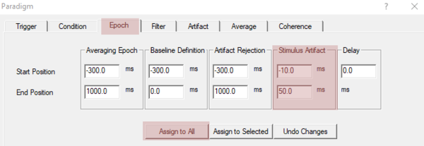
After opening the file in BESA Research you should proceed with data preprocessing as you used to. For example: start with bad channel selection and review data for any parts of the signal that you would like to remove from further analysis due to strong movement. Then perform blink artifact correction either using an automatic or manual approach, as described in BESA Tutorial (chapter 2A for a basic or 10 for an advanced approach). When data is ready for the averaging press the ERP button in the toolbar ribbon. A new dialog box will open. Here the paradigm should be defined (codes assignment and condition creation) as in every classical ERP experiment (check BESA Tutorial 2B for details). Then switch to the tab Epoch. Now set the Averaging Epoch, Baseline Definition and Artifact Rejection interval to match your experiment. As usual please make sure that you have enough signal in the baseline interval, and that events do not overlap. Then in the Stimulus Artifact section set the interval to values which will ensure that the TMS artifact will be not the reason for rejection. In the given example the Stimulus Artifact starts at -10 ms and ends 50 ms after the stimulus trigger. Please make sure you pressed Assignto All or Assign to Selected to make use of the defined seetings.
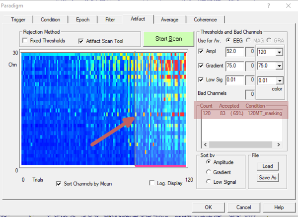
Now switch to the Artifact tab and press the Start Scan button. The Artifact Scan tool is described in more detail in Besa Tutorial chappter 2C. Please adjust the acceptance threshold to remove all non-TMS related artifacts and make sure that there are enough epochs accepted for further analysis. In the given example there are 83 out of 120 events, which should be enough for further analysis. Now in the Average tab press the Average button.
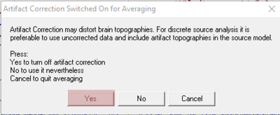
Before the averaging the following warning is presented:
The warning means that the artifact correction (for eyeblink) is currently turned on. Please press Yes button to disable artifact correction for the averaging process. The blink artifact correction can be performed later for the averaged file or during the source analysis. In the given example, blink correction will be applied during source analysis. This approach enables us to investigate the influence of artifact correction on the source waveforms and source localization. Note that if we perform averaging while keeping artifact correction on, this will not be possible since the data will already have been corrected on a single trial level before averaging.
TMS decay artifact reduction
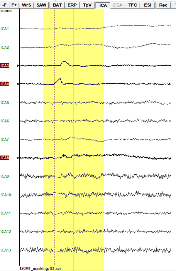
Once the average data is prepared, we need to start the source analysis window. Please highlight the signal of interest by left mouse drag and press the right mouse button on the highlighted area. Now select Source Analysis . In the dialog that appears, you can trim up the interval of interest and set up the filters. Check BESA Tutorial chapter 4C for details. This window should be left open in the background. In the main window of BESA Research (do not close the Source Analysis window!) make sure that all filters are off (in the status bar there should be text Filters off). If any filter is turned on it can be disabled by pressing EdF button and unchecking all filter options. Now ICA decomposition can be started by pressing ICA button and selecting Current Screen. After the computation is finished the data is transformed into independent components. while keeping CTRL button pressed all components that might be related to TMS artifact can be selected. Note that it is possible to select more components than needed. In the presented example three components were selected: ICA3, ICA4, and ICA8. While ICA3 and ICA4 seem clearly related to the TMS decay artifact, the component ICA8 is questionable. It might be either TMS refractory artifact, some noise or neural response. We can verify that later in Source Analysis.
Note that selected components are just example, in any other case, they will look different and will have different labels. Also, the number of TMS related components might be different
The selected components can be sent to the source analysis window by clicking right mouse button on one of the highlighted labels and selecting Send Topography To Source Analysis. The source analysis window will be automatically populated with these independent components and brought to the front.
Source Analysis
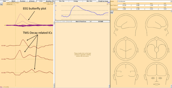
Now the Source analysis module with TMS-decay related Independent Components (IC) along with the EEG waveforms should be visible.
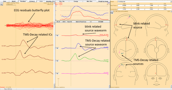
Now previously created blink artifact related topography can be added by opening File menu and select Open Solution... (or Append solution... if some source(s) are already added and needed). In a new dialog window the Artifact Topographies (*.atf,*.art,*.coe) in the Files of type section should be selected. This allows to selct the file with artifact topographies - the file that has exactly the same name as the data file but *.atf extension. By pressing the Open button this topography will be added to the Source Analysis. The TMS related sources can be added pressing right mouse button anywwhere in the TMS-decay related ICs area and selecting Add All ICA Component(s) to Solution. BESA autmoaticaly computes the sources of the TMS-decay related IC and adds them to the solution. Press the Residual button to show EEG signal that is not explained by the model (i.e. is not removed by artifact corection). You can toggle the Data button on and off to compare Residuals with orginal data. It is better however to use residuals for brain source fitting procedure.
By investigating source waveform it is noticeable that the fourth, pink waveform is mostly flat. Therefore third selected IC - the questionable TMS refractory artifact - ICA8 does not underlay any ERP activity. In such situation it is good idea to disable it by pressing switching On button to Off state. The button is located nearby the fourth source waveform.
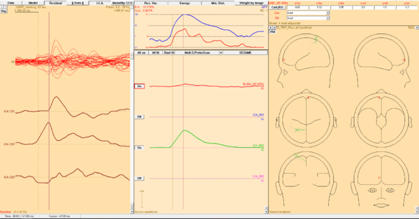
Now have a closer look again on the remaining three source waveforms. The first one - the eyeblink is rather of minor importance here, but since we know that the blinking may occur (and occurred) in the given example we would like to keep this source. The next two source waveforms came from IC indicated as TMS-decay related artifacts. Both sources of these IC - blue and green - are close to each other and have a very similar orientation. Note that they are located over the left hemisphere, nearby central sulcus - see Example. Moreover, we can see that the blue source waveform starts much later (c.a. 50ms after stimulus) while the green starts just after the stimulus onset. This strongly suggest that the blue source should be disabled as well. Now we have two artifact related sources - the red one responsible for the eye-blink, the green one responsible for the TMS-decay artifact. Check out the residuals of EEG - they are resembling classical ERP now!
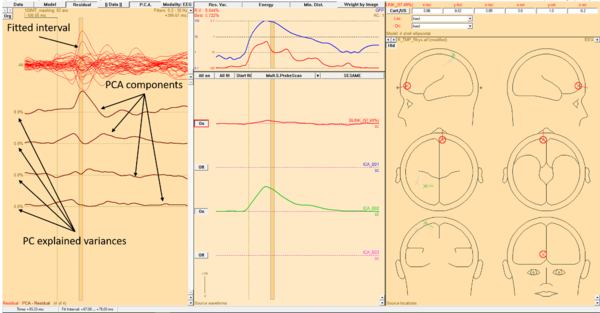
Now we can fit sources that will explain brain activity (this procedure is explained in detail in BESA Tutorial 4). As an initial step, the fitting interval should be selected. It is possible to switch the display from imported ICA to PCA decomposition of the residuals by pressing the ICA button (it will be switched to PCA). For the given example the rising part of residual ERP is selected (note that PCA automatically adjusts to selection). When most of the signal can be explained by one PCA component the good fitting interval is selected.
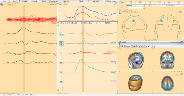
Finally, the sources have to be added and fitted. To add the source double click with left mouse button anywhere in right window area (where heads are drawn). Because it was strong activation (120% rMT) it is possible that there might be cross-talk to the contralateral hemisphere. Therefore the second source should be added. In addition, the symmetry constraint between the first and second source should be set. While the second source is selected, select in Loc: symetric to from drop-down list. Now the second source will be symmetric to the first one after fitting. Press the All fit button to indicate that all cortical sources should be fitted together at the same time. Note that for the artifact related sources cannot be fitted. Press the Start fit button to perform fitting.
The final solution consists of two sources, both located in the precentral cortex, bilaterally. The left source is stronger and starts slightly prior (50ms vs 53ms) to the right source which is plausible concerning the stimulation in given example.
