Difference between revisions of "Review"
(→Scaling) |
|||
| (2 intermediate revisions by one other user not shown) | |||
| Line 2: | Line 2: | ||
|title = Module information | |title = Module information | ||
|module = BESA Research Basic or higher | |module = BESA Research Basic or higher | ||
| − | |version = 6.1 or higher | + | |version = BESA Research 6.1 or higher |
}} | }} | ||
| Line 189: | Line 189: | ||
You can also use the | You can also use the | ||
| − | <span title="Outside the average buffer view, the numeric keys can be used to define tags if a cursor is set: 1-5: Set a tag of type 1-5. 6: Set a comment. 7: Set artifact epoch. 8: Set named epoch. ">'''keyboard shortcuts'''</span> | + | <span title="Outside the average buffer view, the numeric keys can be used to define tags if a cursor is set: 1-5: Set a tag of type 1-5. 6: Set a comment. 7: Set artifact epoch. 8: Set named epoch. ">'''<u>keyboard shortcuts</u>'''</span> |
to set any event. | to set any event. | ||
| Line 615: | Line 615: | ||
[[Image:Review (11).gif]] | [[Image:Review (11).gif]] | ||
| − | For each channel group, there are two controls at the right side of the window. The upper one controls the subset of channels which is displayed, the lower one controls the scaling. To select a subset of a channel group for display, click on the upper of the two buttons. It shows the number of channels which are currently shown, and the total number of channels in that channel group (e.g. Scp, | + | For each channel group, there are two controls at the right side of the window. The upper one controls the subset of channels which is displayed, the lower one controls the scaling. To select a subset of a channel group for display, click on the upper of the two buttons. It shows the number of channels which are currently shown, and the total number of channels in that channel group (e.g. Scp, 31/31). In the dialog box that appears, you can make a fast selection using one of the buttons, or make a precise selection using the rulers. |
| − | The lower of the two buttons for each channel group controls the amplitude scaling. The scaling bar between the buttons shows the scale of the current value, which is shown on the button. To change, for example, the scaling of the EEG channels to 100 µV, click on the lower button of the '<span style="color:#3366ff;">'''Scp'''</span>' channel group, and select 100 µV in the dialog box that appears. | + | The lower of the two buttons for each channel group controls the amplitude scaling. The scaling bar between the buttons shows the scale of the current value, which is shown on the button. The "+" and "-" signs indicate waveforms display polarity that can be changed using the ''View'' setting: ''Show Negativity Up''. Note that by default this setting is enabled and if it is disabled the signs are displayed in red color. |
| + | To change, for example, the scaling of the EEG channels to 100 µV, click on the lower button of the '<span style="color:#3366ff;">'''Scp'''</span>' channel group, and select 100 µV in the dialog box that appears. | ||
For more details about timing, scaling and channel selection controls see the online help chapter <span style="color:#00000a;">''"Review / Reference / Controls / Timing, Scaling, and Channel Selection".''</span> | For more details about timing, scaling and channel selection controls see the online help chapter <span style="color:#00000a;">''"Review / Reference / Controls / Timing, Scaling, and Channel Selection".''</span> | ||
Latest revision as of 12:07, 5 May 2021
| Module information | |
| Modules | BESA Research Basic or higher |
| Version | BESA Research 6.1 or higher |
Contents
The Review Window
BESA Research incorporates many features of the EEGFOCUS program. Therefore, it is a comprehensive EEG review program combining traditional EEG review with new and unmatched tools for digital EEG analysis. The user interface of BESA Research has been designed to allow for very efficient and quick EEG review. BESA Research can store information, i.e. file names, paths and settings of up to 20 EEGs, from one or several subjects. Once you have selected an EEG file, you can use the control push-buttons to:
- switch back and forth between the different selected EEG files
- page forward and backward through the EEG, automatically or manually
- use the event or scroll bar to jump to any marked event or anywhere else in the EEG
- change instantaneously between recorded, virtual, source and user defined montages
- mark, tag, analyze and store any EEG event or segment
- change scales and timing rapidly using toolboxes
- select combinations of scalp, polygraphic, intracranial, and additional channels
Note that BESA Research can also work with MEG. Most of the functions described for EEG are also valid for the processing of MEG signals.
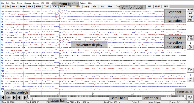
The review window is the main window in BESA Research. It provides access to all important review and analysis features with one or two mouse clicks. The main features are illustrated in the layout figure below. The central part of the window shows the EEG waveforms of the current montage. Around the central display, the menu bar and buttons are grouped for an easy access to the program features.
Overview of the review window
Controls and Push Buttons
Menu bar:
The menu bar is situated at the top of the window. All commands can be selected from one of the submenus which open when you click on one of the headings. Each heading summarizes a set of features for a specific aspect, e.g. artifact correction. All menu items and sub-items are explained in section Menus and in online help chapter "Review / Reference / Menus".
Control ribbon:
Channel group selection:
Scaling and channel selection controls:
Timing push button:
Event bar:
Scroll bar:
Status bar:
Paging controls:
For more details about controls and push buttons see online help chapter "Review / Reference / Controls".
Using the Mouse
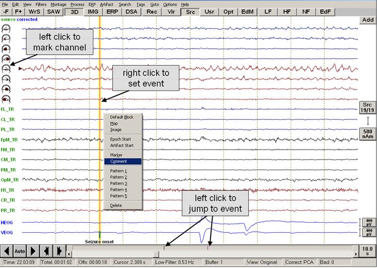
Easy to use mouse operations facilitate working with data files. You can mark specific items by a single click, initiate a map by a double click, or use a right click to open context-optimized menus. The figure below illustrates the main mouse functions. In this example (EEG2.eeg), right temporal-basal seizure onset is shown using the source montage TR_Temporal Region. An automatic eye artifact correction was performed that added two virtual EEG channels for vertical and horizontal eye movements below the montage channels (more information on artifact correction is found in the chapter "Artifact Correction"). The source montage displays the signals from four aspects of the left and right temporal lobes (head symbols: basal, polar, antero-lateral, postero-lateral aspects) and 11 other brain regions (more information on remontaging is found in the chapter "Montage Editor").
The most important mouse functions in the different areas of the review window are:
Basic mouse functions in the review window.
Channel label area:
- Left mouse click: Mark channels for analysis or pattern search (see figure below)
- Right mouse click:
- In source montages, a click on the channel label (or head symbol) at the left of the display opens an image which shows the brain region corresponding to the source channel. Learn more about images in the chapter “Mapping”.
- In the original montage, the right click on the channel label opens a popup menu to define a channel as bad, or to interpolate its signal using the other channels.
Waveform area:
- Left mouse double click: Opens the mapping window and shows the voltage topography at the selected position. Maps can be displayed either as 2D or 3D whole head maps, or as top meridian projection maps. For more details see the chapter “Mapping”.
- Left mouse click: Remove cursor and maps or images, if displayed.
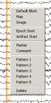
- Right mouse click: Opens a popup menu for marking, adding or deleting events and to start specific processes related to the selected position in the EEG. In the example shown here, a comment was added to indicate seizure onset.
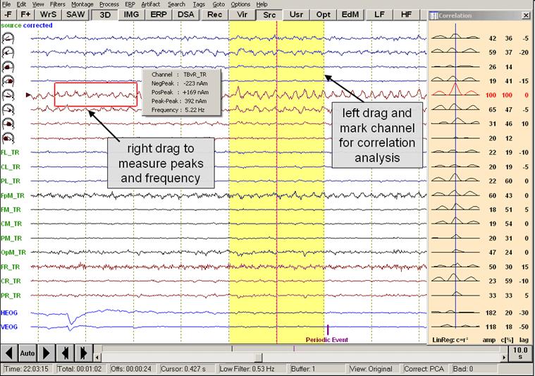
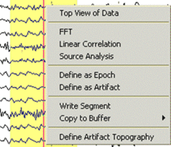
- Left mouse drag: Mark a block for analysis, e.g. FFT or correlation analysis. Right click into the marked block to obtain the special popup menu for processing of marked data blocks.
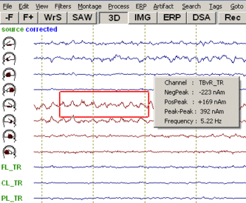
- Right mouse drag: Measure peaks and frequency of marked channels segment (cf. figure below).
Event bar:
- Left mouse click: Jump to events.
- Right mouse click: Display information about events.
Control buttons:
- Left mouse click: Use button.
- Right mouse click: Display information on use of button.
Mouse drag functions in the review window.
The example above illustrates how amplitude peaks and frequencies can be measured using the right mouse drag, and how a block can be marked using the left mouse drag, e.g. for correlation analysis. Please refer to the sections “Measuring Peaks and Frequency” and "Correlation" for detailed explanations.
Paging
Paging through the EEG with BESA Research has several advantages over paging through paper EEG. For example, the default setting in BESA Research is paging with a 10% overlap, which ensures that events at the edge of a page are not overlooked. Larger or smaller paging steps are achieved by just two mouse clicks. You can also jump to any part of the EEG recording by a click into the event bar, switch among various montages using the push buttons, etc.
Paging Using Buttons
You can page through the data using the control push buttons at the bottom left of the review window, as illustrated in the figure below:
The arrows page forward or backward by a whole page. If Paging with Overlap is selected in the program options, paging occurs with a 10% overlap (maximum 1 second). To page through the display automatically, click on the automatic button between the arrow buttons. Then click on the page forward or page backward button, or press the <Space> bar on the keyboard to start paging. Automatic paging may be stopped by clicking the Auto button again, or by pressing the <Space> bar or any key on the keyboard. You can speed up or slow down automatic paging using the menu Options / Paging / Timing of Auto-Page Mode. The arrows at the right are used for paging half a page forward or backward.
Press the arrows on the scrollbar at the bottom of the window (cf. figure below) to step forward or backward by just one second. Clicking into the scrollbar area pages forward or backward in whole page steps (this is also achieved by using the mouse wheel).
These controls are described in more detail in online help chapter "Review / Reference / Menus / Paging Controls".
Paging Using the Keyboard
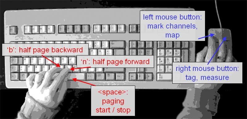
A useful and efficient way to work with BESA Research is to keep the left hand on the keyboard and the right hand on the mouse (see the figure below). You can page through the EEG using the <Space> bar (left hand). Stop paging by pressing the <Space> bar again and press the 'B' key to page back in half page steps, for example, until you see the pattern that made you stop paging. Use the right hand on the mouse to work on the displayed signals, e.g. view maps (left mouse double click), set tags or define epochs and artifacts (right click for popup menu), and perform FFT or linear correlation (drag to mark block and right click for popup menu), etc. To move back by a half page (useful e.g. if a pattern was detected during automatic paging), press the 'B' key. Move forward by a half page with the 'N' key.
For detailed information on additional keyboard paging commands, please refer to online help Chapter "Reference / Controls / Mouse and Keyboard / Keyboard Controls".
Events and Tags
Tagging of the EEG is like making notes on an EEG-printout. Tagged events in a digital EEG are more powerful, since they can be used, for example, for selected viewing of a group of similar events (see online help chapter "Review / Reference / Menus / View / Selected View").
Tags of different kinds can be used to mark time points or ranges of interest, add comments, and define artifact time ranges. All types of tag can be set using the popup menu that appears when the right mouse button is pressed.
Types of Events
There are different types of events that can be tagged manually:
- Markers. These define time points that are used to divide the EEG into gross time ranges, for functions such as: FFT or average between markers.
- Comments. These are text notes that can be placed at any time point in the EEG.
- Epochs. Time ranges of interest with optional labels. These can be selectively viewed excluding all the remaining EEG. This allows for a fast overview over similar epochs.
- Artifacts. Time ranges containing artifacts. These are similar to epochs, with the additional property that they are excluded from averaging and FFT.
- Patterns. These define time points in one of five categories (Pattern 1-5). They may be used for averaging in 5 different buffers and can be defined by the pattern search.
- Triggers. These are defined by an external trigger input or are created from recorded channels by converting pattern tags into triggers from the ERP menu (see help chapter "ERP / Functions... / Managing Triggers / Editing Triggers").
Event Bar
The event bar is located at the bottom of the review window. It shows all events in the data file as vertical lines. Different event types are indicated by different colors. You can view an event description by right click on the corresponding line. Jump to any event by left click on the line.
Setting Events
Most tags are defined at single time points by moving the mouse pointer over the position in the waveforms display, performing a right click, and selecting the tag type from the menu that appears.
Epochs and artifacts are defined when a block has been marked by dragging over a portion of the EEG and pressing the right mouse button. Left and right borders of an epoch/artifact can also be defined at single times by pressing the right mouse button and selecting epoch or artifact. You can page and terminate the pending epoch/artifact by right clicking at another time to mark longer segments.
You can also use the keyboard shortcuts to set any event.
Viewing Events
You can view the type and description of an event in two ways:
- Right click on the vertical line in the event bar which represents the event.
- Jump to the position of the event in the data file by a left click in the event bar (or by using the Goto menu). The event is indicated in the waveform display by a vertical line. Right click into the display just above the event bar with the mouse positioned at the latency of the event.
Remontaging
BESA Research offers three types of montages:
- Recorded (traditional) montages using combinations of the recorded channels
- Virtual (interpolated) montages using combinations of 27, 33 or 81 standard virtual
- Brain source montages using transformations onto virtual electrodes in the brain
Remontaging in BESA Research is conveniently performed by pressing one of the push buttons Rec, Vir, Src or Usr, which provide a shortcut to the Recorded, Virtual, Source and User-Defined submenus of the Montage menu. The push buttons Opt and EdM allow for setting montage options and editing of user-defined and additional montages.
The following standardized montages are provided in BESA Research and can be selected using the Montage menu or the montage push buttons:
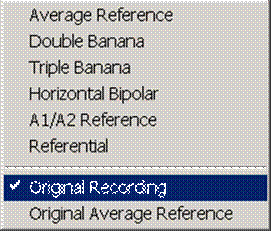
Rec: Recorded (traditional) montages
- Original EEG data: Original Recording.
- Average reference montages: Average Reference, Original Average Reference.
- Longitudinal/horizontal bipolar montages: Double Banana, Triple Banana, Horizontal Bipolar.
- Montages with a single channel reference: A1/A2 Reference, Referential.
Vir: Virtual (interpolated) montages
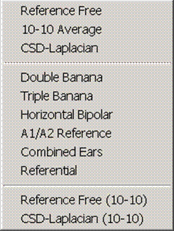
Spherical spline interpolation over the recorded electrodes is used to calculate the voltage at a standard set of 81 virtual electrodes of the 10-10 international electrode system. The average potential over these 81 electrodes is used as the 10-10 average. Combinations between these virtual electrodes are used to calculate standardized montages which are also available if some electrodes are missing or bad:
- Average reference montage: 10-10 Average.
- Longitudinal/horizontal bipolar montages: Double Banana, Triple Banana, Horizontal Bipolar.
- Montages with a single channel reference: A1/A2 Reference, Referential.
- Combined (=averaged) ears reference: Combined Ears.
- Reference-free montage: Reference Free, Reference Free (10-10).
- Current source density montage: CSD-Laplacian, CSD-Laplacian (10-10).
Src: Brain source montages
- Standard brain source montages. See below for further explanation.
Usr: User-defined montages
- Specific user-defined montages created in the Montage Editor or the Source Analysis window. See below for further explanation.
Opt: Montage Options
Recorded, virtual and source montages can be arranged in different systematic orders and groupings using the Opt push button, which provides a shortcut to the Montage / Options menu (see the online help chapter "Review / Reference / Menu / Montage / Options"). Montages can be ordered from:
- left to right depicting lower left, intermediate left, midline, intermediate right and lower right rows of channels with a sequence from anterior to posterior.
- right to left depicting lower right, intermediate right, midline, intermediate left and lower left rows of channels with a sequence from anterior to posterior.
Additionally, montages can be grouped by hemisphere for easier hemispheric comparison or by regions for easier regional comparison.
This allows for convenient comparison of lateralization and location of focal activity across the different montages. This systematic arrangement of traditional, virtual and brain source montages yields a completely new perspective that was not available previously during digital EEG review.
More details on the montage options for regional sources see below.
EdM: Edit Montage
Press this button to open the montage editor. In the Montage Editor, the montage channels can be viewed, edited and combined to new user-defined montages.
Note: You can switch among montages quickly by clicking on the montage push-buttons Rec, Vir, Src, Usr at the top of the main window below the menus. Clicking on the Rec (Vir, Src, Usr) button once switches to the last displayed montage of this category. Clicking again, the popup menu opens to select another montage of this category. BESA Research provides several predefined recorded, virtual and source montages and allows the user to define new montages. User-defined montages are created in the Montage Editor and are stored in binary files. User-defined montage files located in the program subfolder Montages\UserMontages or in the data directory are automatically available from the Montage / User-Defined menu. User-defined montage files located elsewhere can be loaded in the Montage Editor. After loading they are available from the Usr push button too.
The Montage menu provides the same functionality as the push buttons described above, plus the option to show additional channels below the current montage. A brief description of the available montages is given below. For more details see chapter Standard Montages in the help chapter "Montage Editor".
Recorded montages
Press the push button Rec twice or use the menu Montage/Recorded to select a recorded (traditional) montage.
Average Reference
In this traditional montage, the available channels of the Std-27 electrode set are displayed against average reference. The average reference is computed for each time point as the mean voltage over the amplitudes of all scalp electrodes that are not bad. If the common reference used for recording is a single electrode and has been specified, it will be included in the computation of the average reference.
Double Banana
This is a longitudinal bipolar montage containing two left hemispheric, two right hemispheric and one midline longitudinal row of montage channels. Longitudinal rows are arranged from front to back. Predefined montage channels are only displayed if both the channel and reference are available (i.e. recorded and not bad).
Triple Banana
The Triple Banana montage is an extended longitudinal bipolar montage. It has an additional inferior row on each side as compared to the Double Banana montage. Predefined montage channels are only displayed if both the channel and reference are available (i.e. recorded and not bad). The Triple Banana montage is not available if less than 2 inferior electrodes are recorded or defined as ‘good’ on each side.
Horizontal Bipolar
The horizontal bipolar montage contains three transversal rows of montage channels. Transversal rows are arranged from left to right or right to left depending on the settings in Options. Predefined montage channels are only displayed if both the channel and reference are available (i.e. recorded and not bad). In the Horizontal Bipolar montage, available midline electrodes are always displayed even if Midline Channels is set to Off in Montage / Options.
A1/A2 Reference
In this traditional montage, the available left-hemispheric channels of the Std-27 electrode set (except inferior electrodes F9, A1, P9) are displayed against the electrode A1 (or, if A1 is not available, a close channel such as P9 -> T9 -> TP9 -> M1). The available right-hemispheric channels of the Std-27 electrode set (except inferior electrodes F10, A2, P10) are displayed against the electrode A2 (or a close channel such as P10 -> T10 -> TP10 -> M2). The available midline electrodes of the Std-27 electrode set (except Fpz and Oz) are referenced to A1 and A2 (or a close channel), respectively. If neither A1 nor A2 nor any of the close channels are recorded or defined as ‘good’, the A1/A2 Reference montage is not available.
Referential
In this traditional montage, the available channels of the Std-27 electrode set are displayed against a common ‘viewing reference’. The default viewing reference is Cz. The viewing reference can be changed in the Montage Editor (which can be opened using the EdM button in the control ribbon). Any of the electrodes in the EEG file may be used as viewing reference. Note that the common viewing reference is independent of the common reference used for recording.
Original Recording
This montage displays the data as recorded. Note that channels defined as 'bad channels' are shown as a flat grey line. In the other recorded montages, bad channels are not displayed.
If the common reference has been defined, it will be displayed as a flat line as well, since Com minus Com equals zero. The label of the common reference is appended to each channel label.
In this montage, push buttons appear at the upper right of the EEG window for selecting All channel groups or one of the possible channel groups (Scp = scalp EEG, Pgr = polygraphic, Icr = intracranial, MEG = magnetoencephalographic channels). These buttons and the group buttons above the calibration marks may be used to change conveniently between displays of a few selected channels of one group and all groups and channels.
Original Average Reference
In this montage, the scalp electrodes are displayed in the recording sequence, versus common average reference. The average reference is computed for each time point as the mean voltage over the amplitudes of all scalp electrodes that are not bad.
If the common reference is a known single electrode, it will be included in the computation of the average reference. The voltage at the common reference electrode against average reference will be displayed. Note that this is not a flat line!
The Original Recording and Original Average Reference montage have the same sequence of electrodes as the original recorded data. The other recorded montages (as well as the virtual montages) are derived from predefined montage lists based on a standard set of 27 electrodes (Std-27) of the international 10-10 electrode system.
If the common reference used for recording is a known single electrode and has been specified in Edit/ Channel Configuration, the common reference electrode is regarded as part of the recording electrode set. Predefined montage channels using the common reference can be displayed. The common reference will be included in the computation of the average reference. This is not possible, however, for EEG systems using a combination of electrodes as the common reference. e.g. F3/F4.
Note: A predefined recording montage channel is not displayed if either channel or reference are defined as bad in Edit / Bad Channels. Due to missing or bad channels, a predefined recorded montage may be empty. If this is the case, the montage will not be available for selection in the menu. For more details see the help chapter "Montage Editor / Recorded Standard Montages".
Virtual montages
Press the push button Vir twice or use the menu Montage/Virtual to select a virtual (interpolated) montage.
Reference Free
10-10 Average
CSD-Laplacian
Double Banana
Triple Banana
Horizontal Bipolar
A1/A2 Reference
Combined Ears
Referential
Reference Free (10-10)
CSD-Laplacian (10-10)
Virtual montages estimate the voltage at the idealized locations of the standard 27 (81) electrodes on a sphere using spherical spline interpolation. This method is described in Perrin et al. (Electroenceph. clin. Neurophysiol. 72:184-187, 1989); please see chapter “Mapping/ Spherical Spline Maps” for more details. Using this interpolation, EEG traces can also be displayed for missing or bad electrodes. The use of interpolation is indicated by the keyword ‘virtual’ displayed in the upper left corner of the waveform window above the montage channel labels. In principal, spherical spline interpolation is possible outside the area covered by the recording electrodes. Over the lower half of the head, interpolation benefits greatly from the presence of inferior lateral electrodes (F9, A1, P9, F10, A2, P10). Although only a minimum of 2 separate channels with lower lateral electrodes is required, for example A1/A2 or M1/M2, the use of 6 or 4 inferior lateral electrodes is recommended.
For more details regarding virtual montages and virtual electrodes see help chapter Montage Editor / Virtual Standard Montages.
Note: If the number of scalp electrodes is less than 12, spline interpolation and interpolated montages cannot be computed.
Source montages
Press the push button Src twice or use the menu Montage/Source to select a pre-defined source montage. These source montages are available for EEG or MEG, except for the Evoked Potentials montages (EEG only).
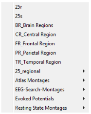
25r and 25s (requires BESA Research 7.1 or higher)
Source montage 25s depicts only the 25 inward radial activities of each region except for the temporal regions below F9/F10 and T9/T10, for which the first orientation of each underlying source was chosen to match the inward net orientations of the temporal polar and basal sublobar surfaces, respectively.
Source montage 25r depicts the activity of each regional source after rotating the first dipole to the maximum of activity over the whole 3 displayed source trace.BR_Brain Regions
CR_Central Region
FR_Frontal Region
PR_Parietal Region
TA_Temporal Lobe
TR_Temporal Region
25_regional (requires BESA Research 7.1 or higher)
Atlas Montages (requires BESA Research 7.1 or higher)
Evoked Potentials
Resting State Montages
BESA Research can transform the scalp EEG into signals of source activity which predominantly reflect the electrical activity of specific regions in the brain. These 'brain source montages' are calculated using specific weighted combinations of the recorded scalp EEG signals. The weights are selected on the basis of multiple dipole models to enhance the activity from one brain region while suppressing the contributions from other brain regions, for example from the contralateral hemisphere. Each new waveform is an optimized linear combination of the measured EEG channels in order to provide a focus onto a particular brain region of interest. On the scalp, the electrical activities of the different brain regions overlap. The brain source montages provide a substantial separation, or deconvolution, of this overlap. Due to the limited number of scalp electrodes, this separation can never be complete. However, separation can be strong enough to make focal activity in the brain visible, by depicting this activity predominantly in the source trace(s) associated with the brain region generating the focal electrical activity.
Brain source montages are provided to facilitate the detection of focal source processes in the brain by reversing the overlap from different brain regions seen at the scalp. If brain activity is focal, i.e. represented predominantly in one source waveform, a large amount of the recorded scalp activity reflected in this trace will originate in the related brain region. If source activity is distributed over several traces, the origin is likely to be more widespread or in areas not precisely modeled by the combination of sources in the selected source montage. Each channel in a brain source montage can be viewed as a 'gross virtual electrode' placed onto a particular brain region.
Standardized brain source montages are defined for the 81 standard 10-10 electrodes. Therefore, the recording montage is first interpolated onto the 81 standard electrodes. Then the source waveforms are calculated using the source montage file.
The standardized source montages are optimized for different brain regions (central, frontal, parietal, temporal). The source montages are composed of dipoles, which predominantly model the activity of the different aspects of the selected brain region, and of regional sources, which largely suppress the source activity arising from other brain regions.
The option Midline Channels in Montage/Options may be used to turn on/off midline source channels. A source channel is considered to be midline if abs(x)<0.2, i.e. if it is located at the midsagittal plane or left/right of the midsagittal plane within 20% of the head radius.
The regional source display type can be changed in Montage/Options. Note that dipoles are indicated by head symbols if Options/Display/Show Heads in Source Montage is selected while regional sources always have green channel labels.
Use the 3D view in the Montage Editor (which can be opened using the EdM button in the control ribbon) to visualize the locations of the dipoles and regional sources in the different source montages or right click on the head symbol/channel label of a source channel to view the brain region and its orientation associated with the selected dipole channel.
For a more detailed description of brain source montages see help chapter Montage Editor / Standard Source Montages.
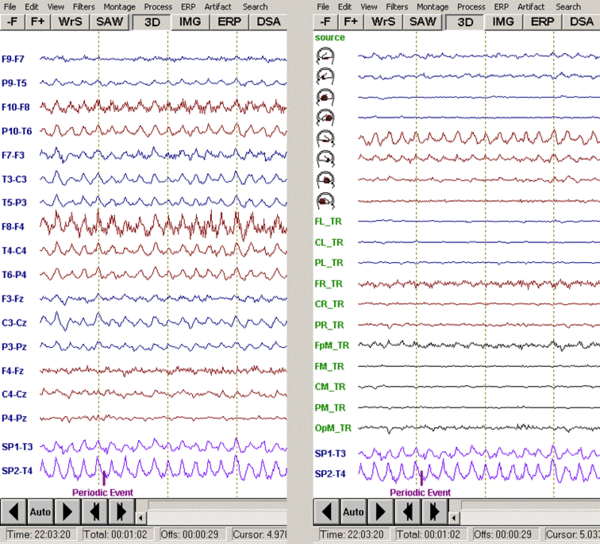
Brain source montages show a much better separation of focal brain activities than scalp montages. For example, if we remontage an EEG showing a temporal lobe seizure best in the horizontal bipolar montage (below left) to a brain source montage (below right, montage TR_Temporal Region), focal source activity is visible at the base and at the tip of the right temporal lobe. Due to the limited spatial resolution of the scalp EEG, a small amount of the activity also appears in other source channels. Nevertheless, the largest activity appears at the base and tip of the right temporal lobe as seen in the source channels. The activity is similar to the activity recorded at the sphenoidal electrodes (SP2-T3 & SP1-T4, below right), but the separation between right and left temporal lobe is larger in the source montage.
Left: Horizontal bipolar montage of the file eeg2.eeg; Right: TR_Temporal Lobe source montage of the same data segment.
The patches of activity shown in color coding in the schematic head views reflect the brain regions onto which the source channels are focused. In other words, each source channel represents a gross 'virtual electrode' placed over the corresponding cortical surface. The size of the patches indicates that the location and extent of the source activity cannot be precisely determined because of the limited spatial resolution. However, the patches reflect a high probability that source activity exists in this brain region provided that one brain region is predominantly active. If multiple patches appear to be active, the distribution of source activity in the brain may be more complex, i.e. more distributed or multifocal, and the distribution has to be interpreted with care.
'Brain source montages' are different from traditional 'source derivations', which subtract the amplitudes of the signal at the adjacent electrodes from the data at a given electrode. Thus, a 'source derivation' shows an approximation of the 'current source density (CSD)' flowing in and out from the skull below a given electrode. BESA Research provides improved 'source derivations' on the basis of 'Laplacian' or current source density montages: CSD-Laplacian and CSD-Laplacian (10-10) montages. In BESA Research, the Laplacian is calculated by spherical spline interpolation. This method provides a more accurate estimate of CSD at any given electrode than the subtraction method using 3-4 surrounding electrodes, especially at the outer electrodes of the scalp electrode array.
Note: If the number of scalp electrodes is less than 12, brain source montages cannot be computed.
User-Defined Montages
Press the push button Usr twice or use the menu Montage/User-Defined to select a user-defined source montage.
User defined montages can be created, edited, saved and reopened in the Montage Editor. For more details see chapter “Montage Editor”.
User montages may contain recorded, virtual and source channels, also in combination. The montage can be saved to file in the Montage Editor in binary format. When saving, the user can decide to put the montage into the folder Montages\UserMontages as a generally available montage or into the data folder as a file specific montage.
Available user montages are displayed by filename in the Montage/User-Defined popup menu. General user montages (stored in Montages\UserMontages) are displayed above the separator in the menu. File specific user montages (stored in the data directory) are displayed below the separator. The latter montages are only displayed if the corresponding data file is currently displayed. It is recommended to use a naming convention similar to the standard brain source montages: AB_Full Name.mtg. AB is abbreviation, which will appear after the label of each channels, e.g. source montage BR_Brain Regions, 1st montage channel = FL_BR.
Additional Channels
Press the push button Add at upper right of the review window or use the menu Montage/Additional Channels to select an additional channel montage.
A set of additional channels can be displayed along with the current montage channels at the bottom of the screen. This is useful, for example, for displaying ECG and other polygraphic channels, and for comparing depth channels with the scalp EEG. Additional channels may be individually filtered (see online help chapter "Review / Reference /Menus / Filters / Polygraphic / Additional Chns") and scaled.
BESA Research ships with a predefined set of additional channel montages which can be selected from the drop-down menu. The corresponding files are stored in the folder Montages\AdditionalChannels. Note that additional channel montages are only available if the labels of the (traditional) additional channels are available or if the (virtual) additional channels can be calculated for the current file.
A detailed description of the predefined additional channel montages is given in the section Standard Montages in the help chapter "Montage Editor".
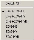
Further additional channel montages may be defined and saved to a file in the Montage Editor. They can also be selected from this menu if they are available for the current file. Use this menu, too, to switch off the currently displayed additional channels.
A commonly used additional channel file can be assigned in the initialization file BESA.ini (entry AdditionalChannelFile in the section [Defaults]). The additional channels will be displayed automatically if they are available, if the entry AdditionalChannelStatus in BESA.ini is set to On and if there is no other additional channel file assigned via the entries in the program database.
Note that this menu can also be conveniently reached from the Add button in the upper right corner of the main window or by a right mouse click on the label of an additional channel.
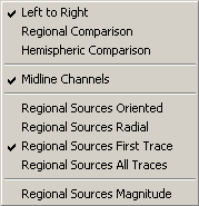
Options
Press the push button Opt twice or use the menu Montage / Options to
- display montages in a sequence from left to right or right to left
- display montages in a sequence for regional comparison
- display montages in a sequence for hemispheric comparison
- switch on/off midline channels
- change the display type of regional source channels
Left to Right
Regional Comparison
Hemispheric Comparison
Midline Channels
Regional Sources Oriented
Regional Sources Radial
Regional Sources First Trace
Regional Sources All Traces
Regional Sources Magnitude
Sequence of Channels in Montages
All montages can be displayed in 6 different systematic orders: Left to Right, Right to Left, Left to Right (or Right to Left) + Hemispheric Comparison, Left to Right (or Right to Left) + Regional Comparison. Select Montage / Options to set the montage order.
If Midline Channels is On in Montage / Options, available midline electrodes are displayed (from Fpz to Oz) in the sequences Left to Right, Right to Left or Regional Comparison. They are not displayed when Hemispheric Comparison is On. In the Horizontal Bipolar montage, available midline electrodes are always displayed.
Color Coding of Montage Channels
Montage channels are systematically colored in BESA Research. Left channels are displayed in dark blue, right channels in dark red. Midline channels are displayed in black. A recorded or virtual montage channel is considered to be midline if channel and reference are at the midline (e.g. Fz-Fcz) or if the reference has no side (e.g. Fz-avr). If the channel is midline but the reference is on the left (right) side, e.g. Fz-A1 (Fz-A2), the montage channel is considered as left (right)-sided, i.e. it is colored in dark blue (red). The same rule applies if the reference is midline but the channel is on the left (right) side, i.e. Fp1-Cz (Fp2-Cz) is displayed in dark blue (red).
In source montages, left channels are displayed in dark blue, right channels in dark red. Midline channels are also displayed in black. A source channel is considered to be midline if abs(x)<0.2, i.e. if it is located in the sagittal plane or left/right of the sagittal plane within 20% of the head radius.
Scaling
The scaling of amplitudes and time intervals is performed using the buttons which are grouped at the righthand side of the waveform display.
Time Scaling
The displayed time can be scaled by clicking the Timing button at the bottom right of the display. The button shows the time interval displayed on the screen. Pressing the button opens the Timing dialog box where epochs between 0.1 s and 60 s can be selected. Using the slider in the dialog, also longer epochs up to 1 hour are possible (depending on sampling rate).
Channel Group Selection
The controls at the top right of the window allow to display All channels of the recording montage or to toggle between subgroups of channels (Scp = scalp, Icr = intracranial, Pgr = polygraphic, MEG). Click on the Add button to display additional channels below the recorded channels. A popup menu appears from which you can choose sets of additional channels. For example, if you choose 'EOG_HV', two virtual eye channels, horizontal and vertical, are calculated from the data and displayed.
Channel Selection and Amplitude Scaling
For each channel group, there are two controls at the right side of the window. The upper one controls the subset of channels which is displayed, the lower one controls the scaling. To select a subset of a channel group for display, click on the upper of the two buttons. It shows the number of channels which are currently shown, and the total number of channels in that channel group (e.g. Scp, 31/31). In the dialog box that appears, you can make a fast selection using one of the buttons, or make a precise selection using the rulers.
The lower of the two buttons for each channel group controls the amplitude scaling. The scaling bar between the buttons shows the scale of the current value, which is shown on the button. The "+" and "-" signs indicate waveforms display polarity that can be changed using the View setting: Show Negativity Up. Note that by default this setting is enabled and if it is disabled the signs are displayed in red color. To change, for example, the scaling of the EEG channels to 100 µV, click on the lower button of the 'Scp' channel group, and select 100 µV in the dialog box that appears.
For more details about timing, scaling and channel selection controls see the online help chapter "Review / Reference / Controls / Timing, Scaling, and Channel Selection".
Filtering
The digital filters in BESA Research are used in addition to the filters set during recording of the digital EEG. It is therefore useful to record the EEG with the largest bandwidth compatible with the sampling rate (e.g. 70 Hz high cutoff at 200 Hz sampling rate), and to use the digital filters in BESA Research to suppress unwanted low and high frequency noise during review, or to enhance the resolution of a periodic pattern by setting the band-pass filter around the frequency of interest.
When a data file is first opened, the filter settings as defined in the initialization file (BESA.ini) are used.
BESA Research supports 4 different filter types: low cutoff, high cutoff, band pass, and notch filter. Filters can conveniently be changed using the push buttons at the top of the waveform display:
Low Filter Button
The LF button opens a popup menu with the available settings for the low cutoff filter. You can choose between time-constant filters and variable filters, where different filter types can be selected (forward, backward, zero phase shift), as well as the slope.
High Filter Button
The popup menu for the HF button provides a selection of frequently used high cutoff filters. Again, it is also possible to use the option 'Variable High Cutoff Filter', where frequency, type, and slope can be selected freely.
Notch Filter Button
A notch filter for suppression of noise in narrow frequency bands is available from the NF button. Click the button to choose between 50 Hz or 60 Hz suppression.
Edit Filters Button
The EdF button starts the dialog box to edit the variable filter settings and to select special band pass and notch filter settings.
In the Filter menu, further commands are available to view the filter response with the current settings, and to adjust baseline settings. In the Filter menu, it is also possible to apply special filtering to polygraphic and additional channels.
For more details see the online help chapter "Review / Reference / Menus / Filters".
Measuring Peaks and Frequency
Amplitude maxima, peak-to-peak differences and the frequency of oscillations of a channel can be measured simply by right clicking and dragging the mouse over the waveform and interval of interest:
The red box indicates the dragging interval and selected channel. The popup window shows the channel label and the measured values for negative peak, positive peak, peak-to-peak amplitude difference, and frequency. If no frequency dominates inside the interval, the frequency is classified as undefined.
To display the amplitude of a channel at a certain time point, place the mouse cursor over the point of interest. The corresponding amplitude will be displayed in the status bar at the bottom of the BESA Research main window.
Correlation Analysis
Correlation analysis provides information about the similarity, relative amplitudes and time delays between one reference channel and the other concurrent waveforms. Using source montages, it can give valuable information about the relationships among the activities of different brain regions. For example, we may want to measure whether a certain pattern in one brain region appears with some time lag and a certain similarity in shape in a different brain region. We can measure the relationship by correlating a segment of interest in a selected channel with all the other channels. BESA Research provides linear and non-linear regression methods (Pijn 1990). These methods can be applied to any montage, but they are most meaningful with source or intracranial waveforms, since scalp waveforms can pick up activity from remote brain regions due to volume conduction effects. When a block of EEG data is marked, you can click the right mouse button and select Linear Correlation from the popup menu. By selecting the menu item Process / Nonlinear Regression, the non-linear regression is calculated for the marked block.
When Linear Correlation is selected, BESA Research computes a correlation function between a reference channel and all the displayed channels, including the reference channel (= autocorrelation). If no specific channel is selected, the channel with the largest signal over the marked block is used as the reference for computing the correlation functions. You may select a different reference channel by clicking on the label or head symbol at the left of the desired reference channel waveform. The correlation window is immediately updated if a new channel is selected as reference.
Correlation is calculated by shifting the reference channel by 30 data sampling points in both directions relative to the other channels. At each shifted point (total 61 points) one value of the correlation function is computed. The squared correlation functions are displayed as waveforms in the correlation window, and their maxima are used to define the time lag or lead of each channel with respect to the reference channel.
A block is marked by holding the left mouse button down to drag over a portion of the EEG in order to mark a specific pattern, or by right-clicking on a peak latency of interest, and selecting “Default block” from the popup menu that appears. If you use the right-click, the default epoch will be marked around the current cursor. The default epoch can be set using the menu Edit / Default Block Epoch. To compute non-linear correlation, use the menu Process / Nonlinear Correlation. The computation of non-linear regression may be slow if the marked epoch is long. You may type any key to stop computing.
Press <Space> to remove the block marking or the cursor. Press <Space> again to continue paging through the EEG.
In the correlation window the following values are displayed (See figure below):
- The squared linear correlation function r², or the non-linear regression coefficient h². The pattern of the marked/largest channel is shifted forward and backward by 30 samples (corresponding to a time lag of ± 150 ms at a sampling rate of 200 Hz).
- The relative value of the maximum signal amplitude in the various channels (amp). 100% is assigned to the amplitude of the largest scalp/source montage channel. Normally, 100% is assigned to the reference channel unless a polygraphic or intracranial channel was used as reference.
- The maximum of the squared correlation coefficient r² or h² (c[%]; 0 - 100%).
- The time lag (positive) or lead (negative) of the maximum of the correlation function relative to the reference channel in milliseconds (lag).
Pattern Search and Averaging
BESA Research offers several possibilities to search for similar events or patterns in the EEG and to average them. Pattern search is initiated by marking a specific block, e.g. from 200 ms before a sharp wave until the following trough, to define a template over one or more selected channels or all displayed channels (spatio-temporal search). Then you decide over which range (whole EEG, between markers etc.) the search will be conducted and which of the pattern tags shall be used. Patterns are detected and tagged automatically, if their correlation with the template exceeds a predefined threshold and if the amplitudes are below artifact threshold or if artifact detection is set to off during search. The correlation threshold and the rejection threshold for artifacts can be adjusted in the menu Search/Options (for more details, see online help chapter "Review / Reference / Menus / Search").
Tags, defined by pattern search or manually, as well as triggers can be used for averaging. Tagged segments or epochs around triggers can be averaged repeatedly while setting different artifact detection thresholds and filters. Search and average can be set to automatic or manual, thus enabling visual inspection of segments prior to tagging or averaging. Search and average offers the following choices:
- Pattern search: uses the signal pattern template in a selected channel or the spatio-temporal pattern over the marked epoch and several marked channels or all displayed channels to search for similar events.
- Tagged event search: used to average similar patterns tagged manually or by pattern
- Trigger events: used to average epochs around external triggers or internally created triggers stored in a separate event file or in the EEG data file
If you want to perform a pattern search, you should mark an epoch first to be used as template. The search can be performed in two ways:
- Spatio-temporal search over all channels: This search type is the default. All channels which are displayed on the screen are used.
- Search for the pattern of one or several specific channels: Mark the channel(s) to be used for the template with a left mouse click on its label (hold down the Ctrl-key to mark more than one channel; cf. section "Using the Mouse").
Before you start searching, you should
- select the type of search – Pattern, Tagged Events, or Triggers – in the Search menu,
- define the Buffer number either in the Tags menu, or more simply by typing the buffer
- set the toggle items in the Search menu (query search, artifact rejection), and the range in the data file which is searched
- for Pattern Search set correlation threshold in Search / Options to approx. 80-85%, if using a single channel template, and to 70-75%, if using a spatio-temporal template with several channels.
Note that even though the search is performed with the template data block size, BESA Research always uses the settings of the Default Block Epoch (set using the Edit menu) to define the length of the average buffer.
The search and/or average starts when a range is selected in the Search menu, or
the button SAW (Search-Average-Write) on the control ribbon is pressed.
Selecting Data Files
If you start reviewing from a patient data base that connects to BESA Research, simply select the recordings you want to review and press the BESA Research icon to open the files.
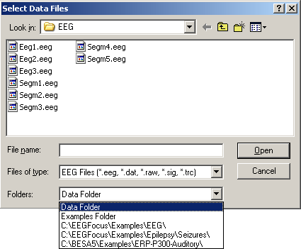
Otherwise, you may open a data file directly from the menu File / Open. This uses a standard Windows File Open dialog that is enhanced by an extra selection box for fast switching between frequently used data folders.
The only special aspect to note is the name extension of the type of data that your own EEG system generates: files are displayed using filters that only show names with particular extensions. These are selected using the dropdown list under "Files of type:". The most commonly used file extensions are summarized under the file type "EEG files". Depending on your EEG system, you may have to switch to a different file type (by selecting one of the entries in the list) the first time you use BESA Research. Your file type setting is remembered for the next time you open a data file.
By holding down the Shift or the Ctrl key you can select several files.
BESA Research allows to open several data files at once. You can switch among the opened files using the file list in the File Menu or the F+ and -F buttons. When a file is closed, the most recently used display settings (filter, no. of secs in the display, etc.) are saved in the database, and restored the next time the file is opened.
Recent Files
The Recent File List (Menu File/Recent Files...) can be used to open recent files. Note also that the files from the previous session can be opened using File/Recent Files.../Open All Files from Previous Session. A keyboard short-cut for this operation is to hold down the Ctrl key and press the -F button.
When BESA Research is started, and no data files have been opened, pressing -F will open the most recent file. If only one file is open, pressing the button again will open the second most recent file.
Data Readers
Data comes in a variety of file formats. Several data formats are controlled by Reader Dlls that are located in the System \ Readers subdirectory of the BESA Research installation. Some readers, although supported, are not installed by default. They can be installed by navigating to the Utilities \ Additional Readers subdirectory of the BESA Research installation with the Windows Explorer, and double-clicking on Install Additional Readers.htm. Here you will find a list of additional readers, and a link to install each reader.
Defining the Channel Configuration
In order to map the data, for source analysis or to transform to virtual montages or source montages, the correct electrode labels or the electrode positions on the head must be known. In the case of MEG, fiducials and, preferentially, additional surface points on the head must be digitized. This information is often not supplied or is incomplete in the original data, although it is strongly recommended to define the correct names and electrode labels to all recording channels during acquisition.
For the case that the channel information is not provided adequately or erroneous, different mechanisms are supplied to enable you to redefine the channel assignment or to read in the required information.
The simplest way to define electrode locations is in terms of the international 10-20 or 10-10 electrode naming system. BESA Research uses a location table to specify where these locations are on a spherical head (see help chapter "Special Topics / Working with Electrodes"). For electrodes at locations deviating from this standard, you can define specific spherical coordinates using the menu Edit / Channel
Configuration / Advanced. Make sure that you check the correct relative location of deviating electrodes using the 3D whole head maps.
More advanced electrode location information is provided with a 3D digitizer. See online help chapter "Special Topics / Working with Electrodes" for a more detailed description how to read digitizer coordinates and other 3D locations (e.g. for MEG).
The following three menu entries can be used to define channel configurations and electrode names and locations:
- Edit / Channel Configuration : Opens a dialog allowing to name channels, define their type (e.g. EEG, Polygraphic, Intracranial), and assign an electrode label or to specify spherical coordinates for EEG electrodes deviating from standard. Channels are listed in the order in which they were recorded. If standard names are supplied for scalp channels, spherical coordinates are assigned automatically by BESA Research
- File / Load Channel Configuration: Loads a file containing a predefined configuration.
- File / Head Surface Points and Sensors / Load Coordinate Files (CTRL-L): Opens a dialog allowing to select channel configurations and digitized coordinates. This dialog is opened automatically when you open a file for the first time and important information is missing. For more details, see help chapter "Special Topics / Working with Electrodes ... / Working with Auxiliary Files". For the rules about when this dialog is opened automatically, see help chapter "Special Topics / Working with Electrodes... / General Reading Rules for Data Files and Auxiliary Files".
Caveat: It is important to check the labels and sequence of channels in the original recorded montage (Montage/Recorded/Original Recording) to make sure that the recording electrode configuration has been correctly protocoled and read from the file header. There may be EEG systems which do not provide this information correctly. Errors may also occur if this information has been entered incorrectly into the recording software. In these cases, you may want to read an electrode file from disk containing your standard or some specific electrode configuration. Such configurations can be edited and stored on disk using the Edit / Channel Configuration menu. It is strongly recommended that you read the Electrodes section in the help chapter "Special Topics" carefully, to make sure that each EEG is associated with the correct labels and sequence of channels, and that the common reference is correctly defined. Otherwise, maps, source images and source montages may be incorrect, and source analysis cannot work properly.
| Review | |
|---|---|
| Source Analysis | |
| Integration with MRI and fMRI | |
| Source Coherence | |
| Export | |
| MATLAB Interface | |
| Special Topics | |
