Difference between revisions of "BESA Research ICA"
| (11 intermediate revisions by 4 users not shown) | |||
| Line 1: | Line 1: | ||
| − | == | + | {{BESAInfobox |
| + | |title = Module information | ||
| + | |module = BESA Research Basic or higher | ||
| + | |version = BESA Research 6.1 or higher | ||
| + | }} | ||
| − | == | + | == Independent Component Analysis == |
| − | + | === ICA Analysis - Main Window === | |
| + | ICA analysis allows decomposing EEG/MEG data into independent components. ICA decomposition is performed on the current screen and can be started from the ICA entry in the menu bar or by pressing the ICA button located in the button menu. The amount of data available in the current screen can be manipulated by using the time scaling button in the bottom right corner of the main window. The ICA menu contains the entries '''Current Screen''', '''Select Components''', '''Load Components''', and '''Options'''. | ||
| − | |||
| + | <!-- [[Image:ICA (1).jpg]] --> | ||
| + | [[Image:ICA_Analysis1a.png|600px]] | ||
| − | |||
| − | <span style="color:#3366ff;"><span | + | Choosing the option <span style="color:#3366ff;">'''ICA / Current Screen'''</span> will lead to the computation of an independent component analysis of the data available on the current screen. Filters are taken into account; bad channels are excluded. The amount of data available in the current screen can be changed by using the time scaling button in the bottom right corner of the main window (max. 1200 s). |
| − | + | In case EEG and MEG data are both available, ICA analysis will only run on the data type that is selected by the EEG/MEG button. Running ICA on combined gradiometer/magnetometer data is not possible. It can only run on one channel type at a time. | |
| + | Before ICA is calculated, the dimensionality of data is optionally reduced by PCA. By default, all PCA components are ignored that explain less than 1% variance. The use of PCA can be switched off or the variance cutoff can be altered by pressing <span style="color:#3366ff;">'''ICA / Options'''</span>. | ||
| − | + | * '''Extended Infomax algorithm''' is based on the maximization of entropy and presents a natural gradient form for the independent components computation. | |
| + | ** Lee TW et al. Independent component analysis using an extended infomax algorithm for mixed sub-Gaussian and super-Gaussian sources. Neural Computation, 11(2), 1999, 409-433 | ||
| + | *'''Second-order blind identification (SOBI)''' algorithm relies on second-order statistics that takes advantage of temporal correlations in the source activities. | ||
| + | **Belouchrani A et al. A blind source separation technique using second-order statistics. IEEE Transactions on Signal Processing, 45(2), 1997, 434-444 | ||
| − | + | [[Image:ica2.png|300px]] | |
| − | + | While ICA is being computed, the current analysis step is displayed in a dialog box along with the changing weights (see figure below). The first ICA step may take longer for many samples than the subsequent steps. In case the number of steps does not change within one second, one full stop is displayed after the step value, two full stops after 2 seconds, 3 full stops after 3 seconds, none after 4 seconds, 1 full stop after 5 seconds, etc. If ICA weights rise too strongly, ICA decomposition restarts with a smaller learning rate. In this case “Restarting” is displayed in the dialogue box. ICA analysis stops when the change of weights from 1 step to the next is smaller than 1.e-6 or after max. 500 steps. ICA analysis can be stopped by pressing the <span style="color:#3366ff;">'''Abort '''</span>button in the dialog box. | |
| − | + | [[Image:ica3.png|300px]] | |
| − | |||
| − | + | The result of the ICA analysis is displayed like a montage (see figure below). ICA waveforms have the labels ICA1 – ICAx. The menu item <span style="color:#3366ff;">'''ICA / Current screen '''</span>is ticked and the ICA button is pressed down. ICA components are sorted in descending order of their explained variance. | |
| − | + | The displayed ICA montage is automatically recomputed whenever ICA options change or the data change, e.g. when paging, filtering, changing the time-range to display, etc. | |
| + | The current ICA decomposition is calculated only taking the data of the current screen into account, but the result is applied on the whole data set. In case the time interval of the data shown on the current screen changes, no automatic recomputation of the ICA decomposition is going to be performed. Instead, an explicit re-calculation is required by clicking the menu item <span style="color:#3366ff;">'''ICA / Current screen'''</span>. | ||
| − | + | Choosing the option '''''Load Components''''', an ASCII file of previously stored or externally calculated ICA topographies can be loaded and displayed. The file must have the format of <span style="color:#ff9c00;">'''<nowiki>*.ica</nowiki>'''</span> files described further down with the '''''Save Topography''''' option. | |
| − | + | [[Image:ica4.png|600px]] | |
| − | + | Right-clicking on an ICA label marks the label and opens a pop-up menu with the following options: | |
| − | |||
| − | + | [[Image:ica5.png|600px]] | |
| − | |||
| − | < | + | The pop-up menu can also be opened when more than one ICA components are selected (using the <span style="color:#3366ff;">'''Ctrl'''</span>-key). |
| − | < | + | <span style="color:#3366ff;">'''Map Topography '''</span>opens the 3D map of the currently selected ICA component (only one component can be selected for this option). The label of the currently selected ICA component is displayed in the bottom left corner of the mapping window. The function ''"Time-Series-Mapping” ''is deactivated when mapping ICA components as the topography does not change over time. Each map is scaled at 120% of its absolute maximum value. |
| − | < | + | The option <span style="color:#3366ff;">'''Define as Artifact Topography'''</span> opens the “''Select Topographies” ''tab of the Artifact Correction Dialog (analogous to pressing ''Artifact / Select''). In this tab, the selected ICA component can be assigned to artifact categories HEOG, VEOG, Blink, EKG, Other1 or Other2. A maximum number of 10 ICA components can be selected at a time when using the artifact categories Other1 and Other2. For the other artifact categories, only 1 ICA component can be selected. After assigning an ICA topography to an artifact category, the topography map and artifact view are shown. Data are not automatically corrected, as this would prompt a new ICA calculation on artifact-corrected data. If the data contain more than one channel type, artifact correction based on ICA components is only available for the channel type on which the ICA was calculated. |
| − | < | + | <span style="color:#3366ff;">'''Send Topography to Source Analysis'''</span> sends all selected ICA topographies to the Source Analysis module as ICA components. This is only possible if the Source Analysis window is open. Within the Source Analysis window, the ICA components can be displayed by pressing the ICA button. Right-clicking on an ICA label allows adding the ICA component(s) to the solution as spatial topographies. |
| − | < | + | <span style="color:#3366ff;">'''Save Topography'''</span> saves all selected ICA topographies in an ASCII-file. This file can be opened in the Source Analysis window or reloaded with ''Load Components. ''File name and path can be selected in the standard saving dialog. The default name is the basename of the current file with the extension “<span style="color:#ff9c00;">'''<nowiki>*.ica</nowiki>'''</span>”. If the data contain different channel types, the filename will be “*_<span style="color:#ff9c00;">'''channeltype.ica'''</span>” (e.g. “*_<span style="color:#ff9c00;">'''Eeg.ica'''</span>”). The format of <span style="color:#ff9c00;">'''<nowiki>*.ica</nowiki>'''</span> files is similar to artifact topography files (<span style="color:#ff9c00;">'''<nowiki>*.atf</nowiki>'''</span>). The first line contains the number of elements (channels) per ICA component (Nchan). The second line contains a list of channel labels and the channel type (Type). The following lines contain the ICA topographies, one topography per line. Each line begins with the corresponding ICA label. Please note that ICA topographies are not average referenced! |
| − | < | + | <pre> |
| + | Nchan= <Number of elements (channels) per ICA topography> | ||
| − | < | + | <List of Nchan channel labels> Type= <BSA channel type als integer> |
| − | < | + | <Label of the first ICA topography, e.g. ICA1> <ICA topography with Nchan elements> |
| − | < | + | <Label of the second ICA topography, e.g. ICA2> <ICA topography with Nchan elements> |
| − | + | ... | |
| − | < | + | <Label of the ith ICA topography, e.g. ICA8> <ICA topography with Nchan elements> |
| + | </pre> | ||
| − | |||
| − | |||
| − | < | + | <span style="color:#3366ff;">'''Export ICA Reconstructed Data Without Selected Components'''</span>: Current Screen creates a new dataset '''without '''the selected ICA components and with the current filter settings only of the data shown on the '''current screen'''. This can be done on the basis of spatial components associated with the ICA topographies analogous to calculating model waveforms from source solutions. The ICA-reconstructed file is saved in BESA binary format with the extension “<span style="color:#ff9c00;">'''<nowiki>*.ica.fsg</nowiki>'''</span>” and contains only those channels for which an ICA was initially computed. If the original data contain more than one channel types, the filename will be labeled according to the channel type used for the reconstruction, e.g. "*_<span style="color:#ff9c00;">'''Eeg.ica.fsg'''</span>”. ICA-reconstructed data can for example be sent to source analysis to only perform source analysis on specific ICA components of interest. |
| − | < | + | <span style="color:#3366ff;">'''Export ICA Reconstructed Data Without Selected Components'''</span>: <span style="color:#3366ff;">'''Whole File'''</span> creates a new dataset '''without''' the selected ICA components and with the current filter settings of the '''entire dataset'''. |
| − | |||
| − | < | + | Operations on the decomposed data can also be performed from the <span style="color:#3366ff;">'''ICA Select'''</span> window (menu item <span style="color:#3366ff;">'''ICA'''</span> <span style="color:#3366ff;">'''/ Select components'''</span> - see figure below). The component name is displayed at the left, the explained variance at the right. When the Extended Infomax algorithm is used, components are sorted by variance. In SOBI algorithm case, the components are sorted by auto-correlation. If the option '''''Map when clicked''''' is checked, the topography of every component is displayed after clicking on it. A component can be selected by double-clicking. It will be marked by an asterisk and it is going to be omitted from the data when exporting with the options '''''Reconstruct: Screen''''' or '''''Reconstruct: Whole File'''''. The button <span style="color:#3366ff;">'''Channel Display'''</span> can be used to only show a part of the available ICA components on the screen. Finally, the button <span style="color:#3366ff;">'''Save Topographies'''</span> can be used to save the selected topographies (see the menu item <span style="color:#3366ff;">'''Save Topography'''</span> from the popup menu above). |
| − | |||
| − | + | [[Image:ica6.png|600px]] | |
| − | + | === ICA Analysis - Source Analysis Window === | |
| − | < | + | ICA components can be used in the Source Analysis window either by sending ICA topographies directly from the main window or by loading an ICA topography file (<span style="color:#ff9c00;">'''<nowiki>*.ica</nowiki>'''</span>) in the Source Analysis window (<span style="color:#3366ff;">'''File /'''</span> <span style="color:#3366ff;">'''Load ICA components'''</span>). |
| − | + | Please note that ICA decomposition is not computed within the Source Analysis window. The Source Analysis window must be opened before sending ICA topographies. The channel configuration of the ICA components and the data in the Source Analysis window must match. When ICA topographies are available in the Source Analysis window, the ICA/PCA toggle button is set to ICA. A waveform for the data-segment available in the Source Analysis window is reconstructed for each ICA component. The amount of variance each ICA component explains is displayed to the right of the according waveform. Additional ICA components can be appended to the ones already present in the Source Analysis window by pressing <span style="color:#3366ff;">'''File / Append ICA components'''</span>. One or more ICA components can be selected by using the<span style="color:#3366ff;">''' shift '''</span>or <span style="color:#3366ff;">'''ctrl'''</span>-key and left-clicking in the ICA component labels. Right-clicking on one or several selected ICA component labels opens a menu with several ICA-related options (see. fig. 1): | |
| − | + | [[Image:ica7.png]] | |
| − | + | ''Figure 1'' | |
| − | |||
| − | + | '''Switch off / on ICA component(s)''' | |
| − | + | Selected ICA components are ignored in the Source Analysis window. Their labels and waveforms are greyed out. If data are sorted by the channel order, un-selected ICA components are automatically sorted to the bottom of the waveform panel. This can be helpful when many ICA components are sent to or loaded in the Source Analysis window. Un-selected ICA-components can be switched back on. | |
| − | + | '''Add selected / all ICA components to solution''' | |
| − | + | One spatial component, corresponding to one ICA topography, per selected ICA label is added to the source solution. The absolute position of the displayed dipoles should not be interpreted as an accurate location, as it is located at the center of gravity of the according map. The source waveform associated with the spatial component is displayed in the Source Waveform panel in the middle of the Source Analysis window. Spatial components are the preferable choice for modelling artifact topographies in | |
| − | + | a source solution (rather than performing source analysis on artifact-corrected data). Spatial components can also be useful if parts of the signal are to be explained that are not of primary interest to the research question in order to reduce the amount of variance that needs to be explained by discrete source analysis. | |
| − | + | [[Category:Research Manual]] | |
| − | + | {{BESAManualNav}} | |
| − | + | ||
| − | + | ||
| − | + | ||
| − | + | ||
| − | + | ||
| − | + | ||
| − | + | ||
| − | + | ||
| − | + | ||
| − | + | ||
| − | + | ||
| − | + | ||
| − | + | ||
| − | + | ||
| − | + | ||
| − | + | ||
| − | + | ||
| − | + | ||
| − | + | ||
| − | + | ||
| − | + | ||
| − | + | ||
| − | + | ||
| − | + | ||
| − | + | ||
| − | + | ||
| − | + | ||
| − | + | ||
| − | + | ||
| − | + | ||
| − | + | ||
| − | + | ||
| − | + | ||
| − | + | ||
| − | + | ||
| − | + | ||
| − | + | ||
| − | + | ||
| − | + | ||
| − | + | ||
| − | + | ||
| − | + | ||
| − | + | ||
| − | + | ||
| − | + | ||
| − | + | ||
| − | + | ||
| − | + | ||
| − | + | ||
| − | + | ||
| − | + | ||
| − | + | ||
| − | + | ||
| − | + | ||
| − | + | ||
| − | + | ||
| − | + | ||
| − | + | ||
| − | + | ||
| − | + | ||
| − | + | ||
| − | + | ||
| − | + | ||
| − | + | ||
| − | + | ||
| − | + | ||
| − | + | ||
| − | + | ||
| − | + | ||
| − | + | ||
| − | + | ||
| − | + | ||
| − | + | ||
| − | + | ||
| − | + | ||
| − | + | ||
| − | + | ||
| − | + | ||
| − | + | ||
| − | + | ||
| − | + | ||
| − | + | ||
| − | + | ||
| − | + | ||
| − | + | ||
| − | + | ||
| − | + | ||
| − | + | ||
| − | + | ||
| − | + | ||
| − | + | ||
| − | + | ||
| − | + | ||
| − | + | ||
| − | + | ||
| − | + | ||
| − | + | ||
| − | + | ||
| − | + | ||
| − | + | ||
| − | + | ||
Latest revision as of 14:23, 5 May 2021
| Module information | |
| Modules | BESA Research Basic or higher |
| Version | BESA Research 6.1 or higher |
Independent Component Analysis
ICA Analysis - Main Window
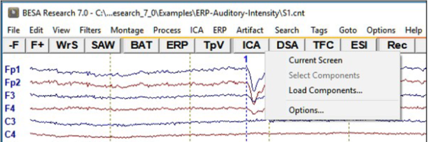
ICA analysis allows decomposing EEG/MEG data into independent components. ICA decomposition is performed on the current screen and can be started from the ICA entry in the menu bar or by pressing the ICA button located in the button menu. The amount of data available in the current screen can be manipulated by using the time scaling button in the bottom right corner of the main window. The ICA menu contains the entries Current Screen, Select Components, Load Components, and Options.
Choosing the option ICA / Current Screen will lead to the computation of an independent component analysis of the data available on the current screen. Filters are taken into account; bad channels are excluded. The amount of data available in the current screen can be changed by using the time scaling button in the bottom right corner of the main window (max. 1200 s).
In case EEG and MEG data are both available, ICA analysis will only run on the data type that is selected by the EEG/MEG button. Running ICA on combined gradiometer/magnetometer data is not possible. It can only run on one channel type at a time.
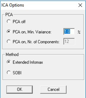
Before ICA is calculated, the dimensionality of data is optionally reduced by PCA. By default, all PCA components are ignored that explain less than 1% variance. The use of PCA can be switched off or the variance cutoff can be altered by pressing ICA / Options.
- Extended Infomax algorithm is based on the maximization of entropy and presents a natural gradient form for the independent components computation.
- Lee TW et al. Independent component analysis using an extended infomax algorithm for mixed sub-Gaussian and super-Gaussian sources. Neural Computation, 11(2), 1999, 409-433
- Second-order blind identification (SOBI) algorithm relies on second-order statistics that takes advantage of temporal correlations in the source activities.
- Belouchrani A et al. A blind source separation technique using second-order statistics. IEEE Transactions on Signal Processing, 45(2), 1997, 434-444
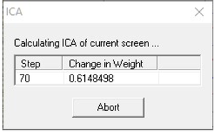
While ICA is being computed, the current analysis step is displayed in a dialog box along with the changing weights (see figure below). The first ICA step may take longer for many samples than the subsequent steps. In case the number of steps does not change within one second, one full stop is displayed after the step value, two full stops after 2 seconds, 3 full stops after 3 seconds, none after 4 seconds, 1 full stop after 5 seconds, etc. If ICA weights rise too strongly, ICA decomposition restarts with a smaller learning rate. In this case “Restarting” is displayed in the dialogue box. ICA analysis stops when the change of weights from 1 step to the next is smaller than 1.e-6 or after max. 500 steps. ICA analysis can be stopped by pressing the Abort button in the dialog box.
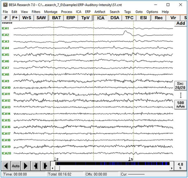
The result of the ICA analysis is displayed like a montage (see figure below). ICA waveforms have the labels ICA1 – ICAx. The menu item ICA / Current screen is ticked and the ICA button is pressed down. ICA components are sorted in descending order of their explained variance.
The displayed ICA montage is automatically recomputed whenever ICA options change or the data change, e.g. when paging, filtering, changing the time-range to display, etc.
The current ICA decomposition is calculated only taking the data of the current screen into account, but the result is applied on the whole data set. In case the time interval of the data shown on the current screen changes, no automatic recomputation of the ICA decomposition is going to be performed. Instead, an explicit re-calculation is required by clicking the menu item ICA / Current screen.
Choosing the option Load Components, an ASCII file of previously stored or externally calculated ICA topographies can be loaded and displayed. The file must have the format of *.ica files described further down with the Save Topography option.
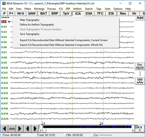
Right-clicking on an ICA label marks the label and opens a pop-up menu with the following options:
The pop-up menu can also be opened when more than one ICA components are selected (using the Ctrl-key).
Map Topography opens the 3D map of the currently selected ICA component (only one component can be selected for this option). The label of the currently selected ICA component is displayed in the bottom left corner of the mapping window. The function "Time-Series-Mapping” is deactivated when mapping ICA components as the topography does not change over time. Each map is scaled at 120% of its absolute maximum value.
The option Define as Artifact Topography opens the “Select Topographies” tab of the Artifact Correction Dialog (analogous to pressing Artifact / Select). In this tab, the selected ICA component can be assigned to artifact categories HEOG, VEOG, Blink, EKG, Other1 or Other2. A maximum number of 10 ICA components can be selected at a time when using the artifact categories Other1 and Other2. For the other artifact categories, only 1 ICA component can be selected. After assigning an ICA topography to an artifact category, the topography map and artifact view are shown. Data are not automatically corrected, as this would prompt a new ICA calculation on artifact-corrected data. If the data contain more than one channel type, artifact correction based on ICA components is only available for the channel type on which the ICA was calculated.
Send Topography to Source Analysis sends all selected ICA topographies to the Source Analysis module as ICA components. This is only possible if the Source Analysis window is open. Within the Source Analysis window, the ICA components can be displayed by pressing the ICA button. Right-clicking on an ICA label allows adding the ICA component(s) to the solution as spatial topographies.
Save Topography saves all selected ICA topographies in an ASCII-file. This file can be opened in the Source Analysis window or reloaded with Load Components. File name and path can be selected in the standard saving dialog. The default name is the basename of the current file with the extension “*.ica”. If the data contain different channel types, the filename will be “*_channeltype.ica” (e.g. “*_Eeg.ica”). The format of *.ica files is similar to artifact topography files (*.atf). The first line contains the number of elements (channels) per ICA component (Nchan). The second line contains a list of channel labels and the channel type (Type). The following lines contain the ICA topographies, one topography per line. Each line begins with the corresponding ICA label. Please note that ICA topographies are not average referenced!
Nchan= <Number of elements (channels) per ICA topography>

<List of Nchan channel labels> Type= <BSA channel type als integer>

<Label of the first ICA topography, e.g. ICA1> <ICA topography with Nchan elements>

<Label of the second ICA topography, e.g. ICA2> <ICA topography with Nchan elements>

...

<Label of the ith ICA topography, e.g. ICA8> <ICA topography with Nchan elements>
Export ICA Reconstructed Data Without Selected Components: Current Screen creates a new dataset without the selected ICA components and with the current filter settings only of the data shown on the current screen. This can be done on the basis of spatial components associated with the ICA topographies analogous to calculating model waveforms from source solutions. The ICA-reconstructed file is saved in BESA binary format with the extension “*.ica.fsg” and contains only those channels for which an ICA was initially computed. If the original data contain more than one channel types, the filename will be labeled according to the channel type used for the reconstruction, e.g. "*_Eeg.ica.fsg”. ICA-reconstructed data can for example be sent to source analysis to only perform source analysis on specific ICA components of interest.
Export ICA Reconstructed Data Without Selected Components: Whole File creates a new dataset without the selected ICA components and with the current filter settings of the entire dataset.
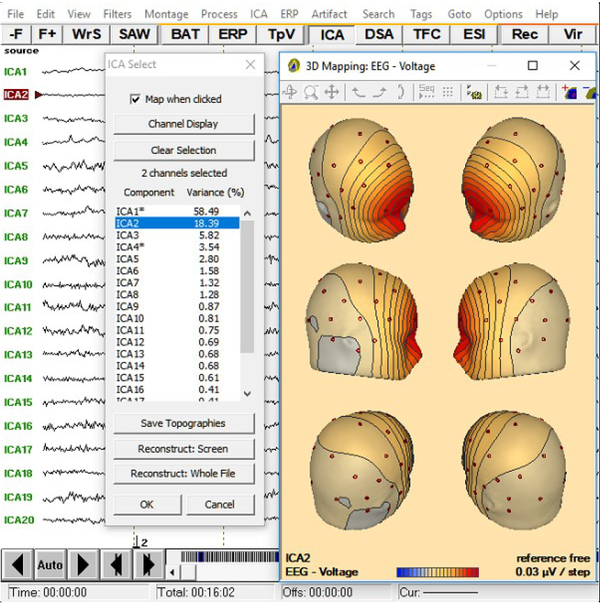
Operations on the decomposed data can also be performed from the ICA Select window (menu item ICA / Select components - see figure below). The component name is displayed at the left, the explained variance at the right. When the Extended Infomax algorithm is used, components are sorted by variance. In SOBI algorithm case, the components are sorted by auto-correlation. If the option Map when clicked is checked, the topography of every component is displayed after clicking on it. A component can be selected by double-clicking. It will be marked by an asterisk and it is going to be omitted from the data when exporting with the options Reconstruct: Screen or Reconstruct: Whole File. The button Channel Display can be used to only show a part of the available ICA components on the screen. Finally, the button Save Topographies can be used to save the selected topographies (see the menu item Save Topography from the popup menu above).
ICA Analysis - Source Analysis Window
ICA components can be used in the Source Analysis window either by sending ICA topographies directly from the main window or by loading an ICA topography file (*.ica) in the Source Analysis window (File / Load ICA components).
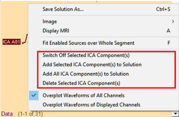
Please note that ICA decomposition is not computed within the Source Analysis window. The Source Analysis window must be opened before sending ICA topographies. The channel configuration of the ICA components and the data in the Source Analysis window must match. When ICA topographies are available in the Source Analysis window, the ICA/PCA toggle button is set to ICA. A waveform for the data-segment available in the Source Analysis window is reconstructed for each ICA component. The amount of variance each ICA component explains is displayed to the right of the according waveform. Additional ICA components can be appended to the ones already present in the Source Analysis window by pressing File / Append ICA components. One or more ICA components can be selected by using the shift or ctrl-key and left-clicking in the ICA component labels. Right-clicking on one or several selected ICA component labels opens a menu with several ICA-related options (see. fig. 1):
Figure 1
Switch off / on ICA component(s)
Selected ICA components are ignored in the Source Analysis window. Their labels and waveforms are greyed out. If data are sorted by the channel order, un-selected ICA components are automatically sorted to the bottom of the waveform panel. This can be helpful when many ICA components are sent to or loaded in the Source Analysis window. Un-selected ICA-components can be switched back on.
Add selected / all ICA components to solution
One spatial component, corresponding to one ICA topography, per selected ICA label is added to the source solution. The absolute position of the displayed dipoles should not be interpreted as an accurate location, as it is located at the center of gravity of the according map. The source waveform associated with the spatial component is displayed in the Source Waveform panel in the middle of the Source Analysis window. Spatial components are the preferable choice for modelling artifact topographies in
a source solution (rather than performing source analysis on artifact-corrected data). Spatial components can also be useful if parts of the signal are to be explained that are not of primary interest to the research question in order to reduce the amount of variance that needs to be explained by discrete source analysis.
| Review | |
|---|---|
| Source Analysis | |
| Integration with MRI and fMRI | |
| Source Coherence | |
| Export | |
| MATLAB Interface | |
| Special Topics | |
