Difference between revisions of "BESA Research Mapping"
| (8 intermediate revisions by 3 users not shown) | |||
| Line 1: | Line 1: | ||
| + | {{BESAInfobox | ||
| + | |title = Module information | ||
| + | |module = BESA Research Basic or higher | ||
| + | |version = BESA Research 6.1 or higher | ||
| + | }} | ||
| + | |||
== <span style="color:#3366ff;"><span style="color:#00000a;">Mapping</span></span> == | == <span style="color:#3366ff;"><span style="color:#00000a;">Mapping</span></span> == | ||
| Line 5: | Line 11: | ||
The 3D mapping window displays whole-head 3D maps that reflect the voltage topography of the ongoing EEG using the current filter settings. The mapping procedure interpolates the EEG voltage or current source density (CSD) values over the whole head on the basis of the spherical splines method with moderate smoothing (Perrin et al. 1989). Maps are projected onto a 3D standardized head surface for a more realistic display of the voltage topography. The head surface was generated by averaging the MRI images of 50 normal subjects after transformation into Talairach space. | The 3D mapping window displays whole-head 3D maps that reflect the voltage topography of the ongoing EEG using the current filter settings. The mapping procedure interpolates the EEG voltage or current source density (CSD) values over the whole head on the basis of the spherical splines method with moderate smoothing (Perrin et al. 1989). Maps are projected onto a 3D standardized head surface for a more realistic display of the voltage topography. The head surface was generated by averaging the MRI images of 50 normal subjects after transformation into Talairach space. | ||
| − | A single 3D map is displayed automatically at the detection peak of a clustered event when selecting an event or cluster in the cluster or hyper cluster displays. The single 3D map is rotated automatically to set the | + | A single 3D map is displayed automatically at the detection peak of a clustered event when selecting an event or cluster in the cluster or hyper cluster displays. The single 3D map is rotated automatically to set the viewpoint to the center of gravity in the map to provide for immediate optimal inspection of dipolar topography. To adjust the viewpoint for a more detailed inspection, use the standard rotation buttons introduced below or use the mouse drag over the head. |
| Line 12: | Line 18: | ||
''2D (left) and 3D (right) voltage maps in single head view at one time point. The EEG shows a detected event in the Av33 user-defined montage.'' | ''2D (left) and 3D (right) voltage maps in single head view at one time point. The EEG shows a detected event in the Av33 user-defined montage.'' | ||
| − | |||
The mapping window appears also when a cursor is set in the EEG data display by clicking onto the EEG. | The mapping window appears also when a cursor is set in the EEG data display by clicking onto the EEG. | ||
| Line 23: | Line 28: | ||
Maps are projected onto a 3D standardized head surface for a more realistic display of voltage topography. The head surface was generated by averaging the MRI images of 24 normal subjects after transformation to the Talairach space using the BrainVoyagerTM software. The standard 10-10 electrodes were adjusted to each individual head using the nasion, pre-auricular points (T9, T10), the inion and the eye canthii as landmarks. Using the spherical spline interpolation over the whole head, reference-free maps are calculated. | Maps are projected onto a 3D standardized head surface for a more realistic display of voltage topography. The head surface was generated by averaging the MRI images of 24 normal subjects after transformation to the Talairach space using the BrainVoyagerTM software. The standard 10-10 electrodes were adjusted to each individual head using the nasion, pre-auricular points (T9, T10), the inion and the eye canthii as landmarks. Using the spherical spline interpolation over the whole head, reference-free maps are calculated. | ||
| − | |||
'''Controls''' | '''Controls''' | ||
| Line 29: | Line 33: | ||
Use the mouse and the keyboard as follows: | Use the mouse and the keyboard as follows: | ||
| − | + | * Click on a map in the standard whole head view with 6 preset viewpoints to display 15 serial maps in the selected view. | |
| − | * | + | |
* Click on a serial map to select a specific time for the display of the 6 standard whole-head maps. | * Click on a serial map to select a specific time for the display of the 6 standard whole-head maps. | ||
| − | |||
| − | |||
| − | |||
[[Image:Mapping (1).png ]] | [[Image:Mapping (1).png ]] | ||
| − | |||
<span style="color:#3366ff;"><span style="color:#00000a;">''3D whole head maps at one latency using 6 standard viewpoints (left) and at a sequence of 15 latencies in serial view (right)''</span></span> | <span style="color:#3366ff;"><span style="color:#00000a;">''3D whole head maps at one latency using 6 standard viewpoints (left) and at a sequence of 15 latencies in serial view (right)''</span></span> | ||
| − | |||
* <span style="color:#3366ff;"><span style="color:#00000a;">Double-click on a standard or serial map to obtain a single enlarged map.</span></span> | * <span style="color:#3366ff;"><span style="color:#00000a;">Double-click on a standard or serial map to obtain a single enlarged map.</span></span> | ||
| − | |||
| Line 50: | Line 47: | ||
| − | * <span style="color:#3366ff;"><span style="color:#00000a;">Drag over the head to rotate or use standard rotation buttons (for more details see</span></span> | + | * <span style="color:#3366ff;"><span style="color:#00000a;">Drag over the head to rotate or use standard rotation buttons (for more details see below).</span></span> |
| + | * <span style="color:#3366ff;"><span style="color:#00000a;">Click or double click on the single head to obtain the 15 serial maps.</span></span> | ||
| + | * <span style="color:#3366ff;"><span style="color:#00000a;">Click on the EEG-Voltage label (bottom left) to display CSD maps. Click on the EEG-C.S.D. label which appears to redisplay voltage maps,</span></span> | ||
| + | * <span style="color:#3366ff;"><span style="color:#00000a;">or type</span></span><span style="color:#3366ff;"><span style="color:#00000a;">''''' M'''''</span></span><span style="color:#3366ff;"><span style="color:#00000a;"> or </span></span><span style="color:#3366ff;"><span style="color:#00000a;">'''''V'''''</span></span><span style="color:#3366ff;"><span style="color:#00000a;"> for voltage maps and </span></span><span style="color:#3366ff;"><span style="color:#00000a;">'''''C'''''</span></span><span style="color:#3366ff;"><span style="color:#00000a;"> for CSD maps.</span></span> | ||
| + | * <span style="color:#3366ff;"><span style="color:#00000a;">When you move the mouse pointer over an electrode, the electrode label (and voltage if in voltage mode) is displayed.</span></span> | ||
| + | * <span style="color:#3366ff;"><span style="color:#00000a;">Left and right cursor keys plot new maps one time unit before or after the current time point. The time units can be adjusted using the </span></span><span style="color:#3366ff;">'''Timing Interval'''</span><span style="color:#3366ff;"><span style="color:#00000a;"> toolbar button.</span></span> [[Image:Mapping (4).gif ]] | ||
| + | * <span style="color:#3366ff;"><span style="color:#00000a;">Up and down cursor keys raise or lower the scaling units of the map display. 3 steps change the scaling by a factor of 2.</span></span> | ||
| + | * <span style="color:#3366ff;"><span style="color:#00000a;">In the sequential and single map views, the head can be rotated, zoomed, or moved, by clicking and dragging with the mouse, depending on which of the </span></span><span style="color:#3366ff;">'''3D Rotate'''</span><span style="color:#3366ff;"><span style="color:#00000a;">, </span></span><span style="color:#3366ff;">'''3D'''</span><span style="color:#3366ff;">'''Magnify'''</span><span style="color:#3366ff;"><span style="color:#00000a;">, </span></span><span style="color:#3366ff;">'''3D Move'''</span><span style="color:#3366ff;"><span style="color:#00000a;"> buttons in the toolbar has been depressed (see below). In addition, the three mouse dragging functions can be controlled directly by holding down the <span style="color:#3366ff;">'''Shift'''</span><span style="color:#3366ff;"><span style="color:#00000a;">,</span></span><span style="color:#3366ff;">''' Ctrl'''</span><span style="color:#3366ff;"><span style="color:#00000a;">, or </span></span><span style="color:#3366ff;">'''Ctrl+Shift'''</span><span style="color:#3366ff;"><span style="color:#00000a;"> keys:</span></span> | ||
| + | * <div style="margin-left:1.259cm;margin-right:0cm;"><span style="color:#3366ff;">'''Shift-Drag'''</span><span style="color:#3366ff;"><span style="color:#00000a;">: Rotate</span></span></div> | ||
| + | * <div style="margin-left:1.259cm;margin-right:0cm;"><span style="color:#3366ff;">'''Ctrl-Drag'''</span><span style="color:#3366ff;"><span style="color:#00000a;">: Move</span></span></div> | ||
| + | * <div style="margin-left:1.259cm;margin-right:0cm;"><span style="color:#3366ff;">'''Shift+Ctrl-Drag'''</span><span style="color:#3366ff;"><span style="color:#00000a;">: Magnify/Zoom</span></span></div> | ||
| − | + | * <span style="color:#3366ff;"><span style="color:#00000a;">Hit the </span></span><span style="color:#3366ff;">'''Escape '''</span><span style="color:#3366ff;"><span style="color:#00000a;">key to close the map window.</span></span> | |
| − | + | ||
| − | + | ||
| − | + | ||
| − | + | ||
| − | + | ||
| − | + | ||
| − | + | ||
| − | + | ||
| − | + | ||
| − | + | ||
| − | + | ||
| − | + | ||
| − | + | ||
| − | + | ||
| − | + | ||
| − | + | ||
| − | + | ||
| − | + | ||
| − | + | ||
| − | + | ||
| − | + | ||
| − | + | ||
| − | + | ||
| − | + | ||
| − | + | ||
| − | + | ||
| − | + | ||
| − | + | ||
| − | + | ||
| − | + | ||
| − | + | ||
| − | + | ||
| − | + | ||
| − | + | ||
| − | + | ||
| − | + | ||
| − | + | ||
| − | + | ||
| − | + | ||
| − | + | ||
| − | + | ||
| − | + | ||
| − | + | ||
| − | + | ||
| − | + | ||
| Line 145: | Line 107: | ||
| − | + | [[Image:Mapping (10).gif ]] | |
| + | |||
| + | |||
| + | * <span style="color:#3366ff;"><span style="color:#00000a;">Toggle between 3D or 2D mapping</span></span> | ||
* <span style="color:#3366ff;"><span style="color:#00000a;">Toggle between whole head mapping and top meridian projection</span></span> | * <span style="color:#3366ff;"><span style="color:#00000a;">Toggle between whole head mapping and top meridian projection</span></span> | ||
* <span style="color:#3366ff;"><span style="color:#00000a;">Toggle between voltage and CSD display</span></span> | * <span style="color:#3366ff;"><span style="color:#00000a;">Toggle between voltage and CSD display</span></span> | ||
| − | * <span style="color:#3366ff;"><span style="color:#00000a;">Toggle between serial and standard maps</span></span> | + | * <span style="color:#3366ff;"><span style="color:#00000a;">Toggle between serial and standard maps</span></span> |
| − | + | * <span style="color:#3366ff;"><span style="color:#00000a;">Toggle whether maps cover the entire head or are cut off at the lower part of the head</span></span> | |
| − | + | ||
| − | + | ||
* <span style="color:#3366ff;"><span style="color:#00000a;">Toggle display of electrodes on the maps</span></span> | * <span style="color:#3366ff;"><span style="color:#00000a;">Toggle display of electrodes on the maps</span></span> | ||
* <span style="color:#3366ff;"><span style="color:#00000a;">Open the online Help</span></span> | * <span style="color:#3366ff;"><span style="color:#00000a;">Open the online Help</span></span> | ||
| Line 165: | Line 128: | ||
<span style="color:#3366ff;"><span style="color:#00000a;">Pressing the right button, </span></span><span style="color:#3366ff;">'''Timing Interval'''</span><span style="color:#3366ff;"><span style="color:#00000a;">, opens a dropdown menu, allowing for the definition of the time interval between sequential maps or the frequency spacing between FFT maps. Voltages and CSD are interpolated to allow for the following standard and custom interval settings:</span></span> | <span style="color:#3366ff;"><span style="color:#00000a;">Pressing the right button, </span></span><span style="color:#3366ff;">'''Timing Interval'''</span><span style="color:#3366ff;"><span style="color:#00000a;">, opens a dropdown menu, allowing for the definition of the time interval between sequential maps or the frequency spacing between FFT maps. Voltages and CSD are interpolated to allow for the following standard and custom interval settings:</span></span> | ||
| + | [[Image:Mapping (12).gif ]] | ||
| − | |||
| − | |||
| − | |||
| − | |||
| − | |||
| − | |||
| − | |||
| − | |||
| − | |||
| − | |||
| − | |||
| − | |||
[[Image:Mapping (13).gif ]] | [[Image:Mapping (13).gif ]] | ||
| Line 207: | Line 159: | ||
<span style="color:#3366ff;"><span style="color:#00000a;">Only the differences are listed here:</span></span> | <span style="color:#3366ff;"><span style="color:#00000a;">Only the differences are listed here:</span></span> | ||
| − | + | # [[Image:Mapping (7).gif ]] <span style="color:#3366ff;"><span style="color:#00000a;">In sequential time view, dragging with the left mouse button over the heads rotates them by 90 degrees. The same is achieved using the </span></span><span style="color:#3366ff;">'''standard rotation'''</span><span style="color:#3366ff;"><span style="color:#00000a;"> toolbar buttons </span></span> | |
| − | # [[Image:Mapping (7).gif ]]<span style="color:#3366ff;"><span style="color:#00000a;">In sequential time view, dragging with the left mouse button over the heads rotates them by 90 degrees. The same is achieved using the </span></span><span style="color:#3366ff;">'''standard rotation'''</span><span style="color:#3366ff;"><span style="color:#00000a;"> toolbar buttons </span></span> | + | |
# <span style="color:#3366ff;"><span style="color:#00000a;">The buttons </span></span><span style="color:#3366ff;">'''3D Rotate'''</span><span style="color:#3366ff;"><span style="color:#00000a;">, </span></span><span style="color:#3366ff;">'''3D Magnify'''</span><span style="color:#3366ff;"><span style="color:#00000a;">, </span></span><span style="color:#3366ff;">'''3D Move'''</span><span style="color:#3366ff;"><span style="color:#00000a;">, are disabled in 2D maps.</span></span> | # <span style="color:#3366ff;"><span style="color:#00000a;">The buttons </span></span><span style="color:#3366ff;">'''3D Rotate'''</span><span style="color:#3366ff;"><span style="color:#00000a;">, </span></span><span style="color:#3366ff;">'''3D Magnify'''</span><span style="color:#3366ff;"><span style="color:#00000a;">, </span></span><span style="color:#3366ff;">'''3D Move'''</span><span style="color:#3366ff;"><span style="color:#00000a;">, are disabled in 2D maps.</span></span> | ||
| − | |||
| Line 217: | Line 167: | ||
<span style="color:#3366ff;"><span style="color:#00000a;">A top meridian projection of the heads can be selected either using the options menu (available from the </span></span><span style="color:#3366ff;">'''Options'''</span><span style="color:#3366ff;"><span style="color:#00000a;"> toolbar button), or by right click with the mouse onto a map. Top meridian projected maps are cut off at a theta value of 110°.</span></span> | <span style="color:#3366ff;"><span style="color:#00000a;">A top meridian projection of the heads can be selected either using the options menu (available from the </span></span><span style="color:#3366ff;">'''Options'''</span><span style="color:#3366ff;"><span style="color:#00000a;"> toolbar button), or by right click with the mouse onto a map. Top meridian projected maps are cut off at a theta value of 110°.</span></span> | ||
| − | <span style="color:#3366ff;"><span style="color:#00000a;">The 2D maps use equipotential line mapping instead of color maps to avoid bias due to the selection of the color scale and in order to emphasize the shape of the voltage or CSD distribution rather than peak areas. The noise in the EEG tends to produce arbitrary shapes in the maps around zero. Therefore, we have spaced the equipotential lines symmetrically around zero at levels of ±1/2, ±3/2, ±5/2....., and shaded negativities below -1/2 of the scaling between lines. This produces maps | + | <span style="color:#3366ff;"><span style="color:#00000a;">The 2D maps use equipotential line mapping instead of color maps to avoid bias due to the selection of the color scale and in order to emphasize the shape of the voltage or CSD distribution rather than peak areas. The noise in the EEG tends to produce arbitrary shapes in the maps around zero. Therefore, we have spaced the equipotential lines symmetrically around zero at levels of ±1/2, ±3/2, ±5/2....., and shaded negativities below -1/2 of the scaling between lines. This produces maps that are less biased by EEG noise, especially when larger scales are used. In 3D maps, an additional color shading is shown for each of the potential compartments.</span></span> |
<span style="color:#3366ff;"><span style="color:#00000a;">A minimum of 12 scalp channels is required to calculate the spline maps. However, a larger array of electrodes is recommended, including electrodes at inferior lateral sites (see help chapter </span></span><span style="color:#3366ff;"><span style="color:#00000a;">''"Special Topics / Working with Electrodes... / Electrodes / Recommendations for Electrode Placement"''</span></span><span style="color:#3366ff;"><span style="color:#00000a;">).</span></span> | <span style="color:#3366ff;"><span style="color:#00000a;">A minimum of 12 scalp channels is required to calculate the spline maps. However, a larger array of electrodes is recommended, including electrodes at inferior lateral sites (see help chapter </span></span><span style="color:#3366ff;"><span style="color:#00000a;">''"Special Topics / Working with Electrodes... / Electrodes / Recommendations for Electrode Placement"''</span></span><span style="color:#3366ff;"><span style="color:#00000a;">).</span></span> | ||
| Line 226: | Line 176: | ||
<span style="color:#3366ff;"><span style="color:#00000a;">The results can be shown in three different ways, which are described in detail below:</span></span> | <span style="color:#3366ff;"><span style="color:#00000a;">The results can be shown in three different ways, which are described in detail below:</span></span> | ||
| − | |||
# <span style="color:#3366ff;"><span style="color:#00000a;">FFT maps of amplitude or power showing the topography at a single frequency</span></span> | # <span style="color:#3366ff;"><span style="color:#00000a;">FFT maps of amplitude or power showing the topography at a single frequency</span></span> | ||
| − | + | # <span style="color:#3366ff;"><span style="color:#00000a;">FFT maps of amplitude or power showing the mean over a preset frequency band</span></span> | |
| − | + | # <span style="color:#3366ff;"><span style="color:#00000a;">Phase maps showing the voltage amplitude topography at a selected frequency and at a specific or different phase angles. Serial phase maps are encoded to show phase delay (in ms) for better comparison with EEG voltage maps, since phase shift is proportional to time delay. Phase maps are only available if the FFT was computed over a single data block.</span></span> | |
| − | + | ||
| − | + | ||
| − | + | ||
| − | + | ||
| − | + | ||
| − | + | ||
| − | + | ||
| Line 243: | Line 185: | ||
<span style="color:#3366ff;"><span style="color:#00000a;">The type of map and further mapping options can be selected from the menus </span></span><span style="color:#3366ff;">'''Map'''</span><span style="color:#3366ff;"><span style="color:#00000a;"> and </span></span><span style="color:#3366ff;">'''Options/Mapping'''</span><span style="color:#3366ff;"><span style="color:#00000a;"> in the FFT window.</span></span> | <span style="color:#3366ff;"><span style="color:#00000a;">The type of map and further mapping options can be selected from the menus </span></span><span style="color:#3366ff;">'''Map'''</span><span style="color:#3366ff;"><span style="color:#00000a;"> and </span></span><span style="color:#3366ff;">'''Options/Mapping'''</span><span style="color:#3366ff;"><span style="color:#00000a;"> in the FFT window.</span></span> | ||
| − | |||
<div style="color:#00000a;">[[Image:Mapping (15).gif ]]</div> | <div style="color:#00000a;">[[Image:Mapping (15).gif ]]</div> | ||
| Line 252: | Line 193: | ||
<span style="color:#3366ff;"><span style="color:#00000a;">Note: Mapping of FFT spectra is only possible if there are at least 12 electrodes!</span></span> | <span style="color:#3366ff;"><span style="color:#00000a;">Note: Mapping of FFT spectra is only possible if there are at least 12 electrodes!</span></span> | ||
| − | |||
| − | |||
| − | |||
| − | |||
| − | |||
| − | |||
<span style="color:#3366ff;"><span style="color:#00000a;">'''Topographies at a given frequency and at a series of frequencies'''</span></span> | <span style="color:#3366ff;"><span style="color:#00000a;">'''Topographies at a given frequency and at a series of frequencies'''</span></span> | ||
| Line 311: | Line 246: | ||
| − | + | [[Image:Mapping (17).gif ]] | |
| − | + | ||
| − | + | ||
| − | + | ||
| − | + | ||
| − | + | ||
| − | + | ||
| − | + | ||
| − | + | ||
| − | + | ||
| − | + | ||
| − | + | ||
| − | + | ||
| − | + | ||
| − | + | ||
| − | + | ||
| − | + | ||
| − | + | ||
| − | + | ||
| − | + | ||
| − | + | ||
| − | + | ||
| − | + | ||
| − | + | ||
| − | + | ||
| − | + | ||
| − | + | ||
| − | + | ||
| − | + | ||
| − | + | ||
| − | + | ||
| − | + | ||
| − | + | ||
| − | + | ||
| − | + | ||
| Line 353: | Line 254: | ||
<span style="color:#3366ff;"><span style="color:#00000a;">Phase maps cannot be generated for mean spectra: generating means over frequencies or over a set of FFTs causes phase information to be lost. Thus, phase maps cannot be shown for frequency bands or for the result of mean FFTs between markers.</span></span> | <span style="color:#3366ff;"><span style="color:#00000a;">Phase maps cannot be generated for mean spectra: generating means over frequencies or over a set of FFTs causes phase information to be lost. Thus, phase maps cannot be shown for frequency bands or for the result of mean FFTs between markers.</span></span> | ||
| − | + | <span style="color:#3366ff;"><span style="color:#00000a;">'''Toggling between EEG/MEG FFT maps'''</span></span> | |
| − | <span style="color:#3366ff;"><span style="color:#00000a;">''Toggling between EEG/MEG FFT maps''</span></span> | + | |
| − | + | ||
<span style="color:#3366ff;"><span style="color:#00000a;">For a combined EEG and MEG measurement, the type of map (either EEG or MEG) that is currently selected is displayed in the left upper corner of the FFT window. Initially EEG is displayed. Click on the text to toggle between EEG and MEG FFT maps. A currently open map window will be updated immediately.</span></span> | <span style="color:#3366ff;"><span style="color:#00000a;">For a combined EEG and MEG measurement, the type of map (either EEG or MEG) that is currently selected is displayed in the left upper corner of the FFT window. Initially EEG is displayed. Click on the text to toggle between EEG and MEG FFT maps. A currently open map window will be updated immediately.</span></span> | ||
| − | |||
| − | |||
| − | |||
| − | |||
| − | |||
| − | |||
| − | |||
| − | |||
| − | |||
| − | |||
| − | |||
| − | |||
| − | |||
| − | |||
| − | |||
| − | |||
| − | |||
| − | |||
| − | |||
| − | |||
| − | |||
| − | |||
| − | |||
| − | |||
| − | |||
| − | |||
| − | |||
| − | |||
| − | |||
| − | |||
| − | |||
| − | |||
| − | |||
| − | |||
| − | |||
| − | |||
=== <span style="color:#3366ff;"><span style="color:#00000a;">Source Images</span></span> === | === <span style="color:#3366ff;"><span style="color:#00000a;">Source Images</span></span> === | ||
| Line 414: | Line 277: | ||
<span style="color:#3366ff;"><span style="color:#00000a;">Using the arrow buttons at the top, you can change the latency range which is displayed, and the interval between subsequent maps:</span></span> | <span style="color:#3366ff;"><span style="color:#00000a;">Using the arrow buttons at the top, you can change the latency range which is displayed, and the interval between subsequent maps:</span></span> | ||
| − | + | * <span style="color:#3366ff;"><span style="color:#00000a;">Left group of arrow buttons: These buttons jump 7 maps forward (or backward) in time (i.e. the last (or first) map in the sequence becomes the central map.</span></span> | |
| − | * <span style="color:#3366ff;"><span style="color:#00000a;">Left group of arrow buttons: These buttons jump 7 maps forward (or backward) in time | + | * <span style="color:#3366ff;"><span style="color:#00000a;">Right group of arrow buttons: These buttons increase (or decrease) the interval between the maps in the sequence </span></span> |
| − | + | ||
| − | + | ||
| − | + | ||
| − | + | ||
| − | + | ||
| − | + | ||
| − | + | ||
| − | + | ||
| − | + | ||
<div style="color:#00000a;"></div> | <div style="color:#00000a;"></div> | ||
| Line 439: | Line 293: | ||
<span style="color:#3366ff;"><span style="color:#00000a;">''Why use spherical spline interpolation?''</span></span> | <span style="color:#3366ff;"><span style="color:#00000a;">''Why use spherical spline interpolation?''</span></span> | ||
| − | |||
<span style="color:#3366ff;"><span style="color:#00000a;">Spherical spline maps present an interpolation of the potential distribution at the scalp with zero integral over the whole head and maximum smoothness (Pascual et al. 1988; Pernier et al. 1989). Based on these assumptions, the spherical spline method provides an optimal interpolation within the area covered by electrodes on the scalp as well as an optimal extrapolation to the part of the sphere not covered by electrodes. The strength of the spherical spline method stems from the underlying physical boundary</span></span> | <span style="color:#3366ff;"><span style="color:#00000a;">Spherical spline maps present an interpolation of the potential distribution at the scalp with zero integral over the whole head and maximum smoothness (Pascual et al. 1988; Pernier et al. 1989). Based on these assumptions, the spherical spline method provides an optimal interpolation within the area covered by electrodes on the scalp as well as an optimal extrapolation to the part of the sphere not covered by electrodes. The strength of the spherical spline method stems from the underlying physical boundary</span></span> | ||
| Line 456: | Line 309: | ||
<span style="color:#3366ff;"><span style="color:#00000a;">BESA uses an implementation of the spherical splines method as described in the publication 'Spherical splines for scalp potential and current density mapping' by Perrin et al. (Electroencephalogr. Clin. Neurophysiol. 72:184-187, 1989). BESA uses 4th order spherical splines, including Legendre polynomials up to 50th degree. The smoothing constant l can be specified from the menu entry </span></span><span style="color:#3366ff;">'''Options / Mapping / Spline Interpolation Smoothing Constant.'''</span> | <span style="color:#3366ff;"><span style="color:#00000a;">BESA uses an implementation of the spherical splines method as described in the publication 'Spherical splines for scalp potential and current density mapping' by Perrin et al. (Electroencephalogr. Clin. Neurophysiol. 72:184-187, 1989). BESA uses 4th order spherical splines, including Legendre polynomials up to 50th degree. The smoothing constant l can be specified from the menu entry </span></span><span style="color:#3366ff;">'''Options / Mapping / Spline Interpolation Smoothing Constant.'''</span> | ||
| − | |||
=== <span style="color:#3366ff;"><span style="color:#00000a;">Current Source Density (CSD)</span></span> === | === <span style="color:#3366ff;"><span style="color:#00000a;">Current Source Density (CSD)</span></span> === | ||
| Line 465: | Line 317: | ||
<span style="color:#3366ff;"><span style="color:#00000a;">'''The surface Laplacian operator '''</span></span><span style="color:#3366ff;"><span style="color:#00000a;">(second spatial derivative of the voltage distribution in tissue) calculates the volume current flow out of the brain through the skull into the skin. That is why we use the term </span></span><span style="color:#3366ff;"><span style="color:#00000a;">'''Current Source Density '''</span></span><span style="color:#3366ff;"><span style="color:#00000a;">(CSD). The CSD montage will show a large signal if the cortical surface (convexity) is active. This corresponds to a radial superficial dipole.</span></span> | <span style="color:#3366ff;"><span style="color:#00000a;">'''The surface Laplacian operator '''</span></span><span style="color:#3366ff;"><span style="color:#00000a;">(second spatial derivative of the voltage distribution in tissue) calculates the volume current flow out of the brain through the skull into the skin. That is why we use the term </span></span><span style="color:#3366ff;"><span style="color:#00000a;">'''Current Source Density '''</span></span><span style="color:#3366ff;"><span style="color:#00000a;">(CSD). The CSD montage will show a large signal if the cortical surface (convexity) is active. This corresponds to a radial superficial dipole.</span></span> | ||
| − | <span style="color:#3366ff;"><span style="color:#00000a;">If the brain activity is in a fissure (tangential dipole) the CSD signal is much weaker. The current | + | <span style="color:#3366ff;"><span style="color:#00000a;">If the brain activity is in a fissure (tangential dipole) the CSD signal is much weaker. The current flow in a tangential direction, so you will see two peaks of opposite polarity in the CSD maps, corresponding to where the volume current is leaving (+) and entering (-) the skull. The two zones of maximum current are closer together than in voltage maps, because the voltage is an integral over current source density.</span></span> |
<span style="color:#3366ff;"><span style="color:#00000a;">Units of current source density are voltage per unit distance per unit distance (e.g. µV/cm²) or current per unit area (e.g. µA/cm²). Conversion from the second derivative of the voltage to current units is a complex issue because this requires knowledge about conductivities of the skull and scalp surfaces. Therefore, µV/cm² is used, i.e. just the second derivative of the voltage distribution.</span></span> | <span style="color:#3366ff;"><span style="color:#00000a;">Units of current source density are voltage per unit distance per unit distance (e.g. µV/cm²) or current per unit area (e.g. µA/cm²). Conversion from the second derivative of the voltage to current units is a complex issue because this requires knowledge about conductivities of the skull and scalp surfaces. Therefore, µV/cm² is used, i.e. just the second derivative of the voltage distribution.</span></span> | ||
| + | === Mapping/Tutorial === | ||
| − | === <span style="color:#3366ff;"><span style="color:#00000a;"> | + | <span style="color:#3366ff;"><span style="color:#00000a;">The aim of this section is to generate map and source image displays. It is assumed that you have loaded EEG2 (data: sub-folder </span></span><span style="color:#ff9c00;">'''Examples\EEG_Focus\eeg2.eeg'''</span><span style="color:#3366ff;"><span style="color:#00000a;">, electrode file: </span></span><span style="color:#ff9c00;">'''eeg2.elb'''</span><span style="color:#3366ff;"><span style="color:#00000a;">, filters variable 1.6-35 Hz, </span></span><span style="color:#3366ff;"><span style="color:#00000a;">''Org ''</span></span>montage). |
| − | |||
| + | '''Basic steps''' | ||
| − | + | * 1. Move to the '''periodic pattern''' in EEG2 by clicking on the event marked at the middle of the event bar. | |
| − | + | [[Image:Mapping (21).gif]] | |
| + | * 2. Double click on any of the peak deflections to set a mark at the cursor position. A '''vertical bar''' (dark red on a yellow background) will be set, and '''Voltage maps''' will be displayed automatically. The latency will be shown at the bottom of the map window. | ||
| − | |||
| + | [[Image:Mapping (22).gif]] | ||
| − | |||
| + | * <span style="color:#3366ff;"><span style="color:#00000a;">3. Repeat double clicking on several different peaks to view the maps at different latencies. Type the </span></span><span style="color:#3366ff;">'''Esc'''</span><span style="color:#3366ff;"><span style="color:#00000a;"> key to close the map window.</span></span> | ||
| + | * <span style="color:#3366ff;"><span style="color:#00000a;">4. Press the </span></span><span style="color:#3366ff;">'''SRC'''</span><span style="color:#3366ff;"><span style="color:#00000a;"> button, and from the dropdown menu select the</span></span><span style="color:#3366ff;"><span style="color:#00000a;">'' TR-Temporal Region ''</span></span><span style="color:#3366ff;"><span style="color:#00000a;">montage. Double-click on one of the peaks to display voltage maps again.</span></span> | ||
| + | * <span style="color:#3366ff;"><span style="color:#00000a;">5. Press the </span></span><span style="color:#3366ff;">'''IMG '''</span><span style="color:#3366ff;"><span style="color:#00000a;">button, so that it remains down. The map display changes to </span></span><span style="color:#3366ff;"><span style="color:#00000a;">'''source images'''</span></span><span style="color:#3366ff;"><span style="color:#00000a;"> calculated from the magnitude of the source channels at the marked latency.</span></span> | ||
| − | + | [[Image:Mapping (23).gif]] | |
| − | |||
| − | < | + | * <span style="color:#3366ff;"><span style="color:#00000a;">6. Repeat double clicking on several different peaks to view the source images at different latencies. Click on the up/down arrows to the right or left of the scaling bar below the images to increase or decrease scaling.</span></span> |
| + | * <span style="color:#3366ff;"><span style="color:#00000a;">7. Select a prominent peak and double click to display the source images. On the keyboard press the </span></span><span style="color:#3366ff;">'''left and right arrows'''</span><span style="color:#3366ff;"><span style="color:#00000a;"> to display source images at the next/previous sampling point or 5 ms later/earlier. Click on the up/down arrows right or left of the scale bar to increase or decrease scaling.</span></span> | ||
| + | * <span style="color:#3366ff;"><span style="color:#00000a;">8. The latency should still be marked from the previous step. Type M to display voltage maps instead of the source images at the currently marked latency, and type 'i' again if you want to view the source images.</span></span> | ||
| + | * <span style="color:#3366ff;"><span style="color:#00000a;">9. Press the </span></span><span style="color:#3366ff;">'''IMG'''</span><span style="color:#3366ff;"><span style="color:#00000a;"> button again. Source images are switched off and 3D amplitude maps are displayed. Click on a map to convert the display from</span></span><span style="color:#3366ff;"><span style="color:#00000a;">''' standard'''</span></span><span style="color:#3366ff;"><span style="color:#00000a;"> to </span></span><span style="color:#3366ff;"><span style="color:#00000a;">'''sequential'''</span></span><span style="color:#3366ff;"><span style="color:#00000a;"> view.</span></span> | ||
| + | * <span style="color:#3366ff;"><span style="color:#00000a;">10. Click and drag on a map to rotate the head to a new position. Note how all the maps in the sequential view are redrawn in the new position.</span></span> | ||
| + | * <span style="color:#3366ff;"><span style="color:#00000a;">11. Try out the various controls on the 3D map toolbar (at the top of the map window. See chapter </span></span><span style="color:#3366ff;"><span style="color:#00000a;">''“3D Maps”''</span></span><span style="color:#3366ff;"><span style="color:#00000a;"> for descriptions of the toolbar controls. Finally, switch back to 2D maps by disengaging the </span></span><span style="color:#3366ff;">'''3D'''</span><span style="color:#3366ff;"><span style="color:#00000a;"> button.</span></span> | ||
| + | *<span style="color:#3366ff;"><span style="color:#00000a;">12. You may also select </span></span><span style="color:#3366ff;"><span style="color:#00000a;">'''Voltage maps'''</span></span><span style="color:#3366ff;"><span style="color:#00000a;"> or any other process from the </span></span><span style="color:#3366ff;">'''Process '''</span><span style="color:#3366ff;"><span style="color:#00000a;">menu when a latency is marked and a source montage is displayed. Note that voltage maps can be displayed in all montages by clicking anywhere on the EEG, if the </span></span><span style="color:#3366ff;">'''IMG'''</span><span style="color:#3366ff;"><span style="color:#00000a;"> button is not down.</span></span> | ||
| + | * <span style="color:#3366ff;"><span style="color:#00000a;">13. Select average reference montage </span></span><span style="color:#3366ff;"><span style="color:#00000a;">'''''Avr'''''</span></span><span style="color:#3366ff;"><span style="color:#00000a;">, and repeat double clicking on several different peaks (Note that typing 'i' will change to the last active source montage again and display source images).</span></span> | ||
| + | * <span style="color:#3366ff;"><span style="color:#00000a;">14. Display voltage maps and make sure that electrodes are shown (if not, right-click on one of the heads, and select </span></span><span style="color:#3366ff;">'''Show Electrodes'''</span><span style="color:#3366ff;"><span style="color:#00000a;"> from the popup menu. If selected, the electrode locations, projected on the 6 different views of the head model, will be displayed. Select </span></span><span style="color:#3366ff;">'''Top Meridian Projection'''</span><span style="color:#3366ff;"><span style="color:#00000a;"> from the </span></span><span style="color:#3366ff;">'''Options/Mapping'''</span><span style="color:#3366ff;"><span style="color:#00000a;"> menu to display a sequence of maps in equidistant steps relative to the marked latency. Note that the sequential maps present top views in meridian projection down to the level of F9, T9, P9, F10, T10, P10. By using spline interpolation, the maps are capable of covering this wider range as compared to traditional maps. Deselect top view sequential maps again.</span></span> | ||
| − | |||
| − | < | + | <span style="color:#3366ff;"><span style="color:#00000a;">'''Map and source image sequences'''</span></span> |
| + | * <span style="color:#3366ff;"><span style="color:#00000a;">1. Select file </span></span><span style="color:#ff9c00;">'''segm1.eeg'''</span><span style="color:#3366ff;"><span style="color:#00000a;"> and select the </span></span><span style="color:#3366ff;"><span style="color:#00000a;">''TA_Temporal Lobe ''</span></span><span style="color:#3366ff;"><span style="color:#00000a;">source montage. Engage the </span></span><span style="color:#3366ff;">'''IMG '''</span><span style="color:#3366ff;"><span style="color:#00000a;">button. The </span></span><span style="color:#3366ff;"><span style="color:#00000a;">'''''TA '''''</span></span><span style="color:#3366ff;"><span style="color:#00000a;">montage includes basal, anterior, and lateral temporal brain regions. Note how this montage suggests the onset of the spike in the left basal temporal lobe, with subsequent components in the anterior tip and lateral surface of the left temporal lobe.</span></span> | ||
| + | * <span style="color:#3366ff;"><span style="color:#00000a;">2. Double click on the positive (upward-going) peak on the third channel from the top of the screen (left lateral temporal lobe). The source image will be displayed.</span></span> | ||
| + | * <span style="color:#3366ff;"><span style="color:#00000a;">3. Click on the left lateral head view (top left source image). Note how the cursor changes to a hand over areas where clicks initiate an action. A series of 15 equidistant source images around the cursor latency will be displayed.</span></span> | ||
| − | |||
| − | + | [[Image:Mapping (24).gif]] | |
| − | |||
| − | < | + | * 4. Click on the left/right arrows at the left at the top of the map display to page 7 maps backward or forward. |
| + | * 5. Click on the left/right arrow at the right at the top of the map display to decrease or increase the interval between the sequential maps. Alternatively, you may set the interval in <span style="color:#3366ff;">'''Interval between Sequential Maps'''</span> in the <span style="color:#3366ff;">'''Options/Mapping'''</span> menu. | ||
| + | * 6. Type 'm' or 'v' to view a sequence of amplitude maps in the same time range (click the rotate-left button and the rotate-up-down button twice each to arrive at the head positions shown below): | ||
| − | |||
| − | + | [[Image:Mapping (25).gif]] | |
| − | |||
| − | |||
| − | |||
| − | |||
| − | |||
| − | |||
| − | |||
| − | |||
| − | |||
| − | |||
| − | |||
| − | |||
| − | |||
| − | |||
| − | |||
| − | |||
| − | |||
| − | |||
| − | |||
| − | |||
| − | |||
| − | |||
| − | |||
| − | |||
| − | |||
| − | |||
| − | |||
| − | |||
| − | |||
| − | |||
| − | |||
| − | |||
| − | |||
| − | |||
| − | |||
| − | |||
| − | |||
| − | |||
| − | |||
| − | |||
| − | |||
| − | |||
| − | |||
| − | |||
| − | |||
| − | |||
| − | |||
| − | |||
| − | |||
| − | |||
| − | |||
| − | |||
| − | |||
| − | |||
| − | |||
| − | |||
| − | |||
| − | |||
| − | |||
| − | |||
| − | |||
| − | |||
| − | |||
| − | |||
| − | |||
| − | |||
| − | |||
| − | |||
| − | |||
| − | |||
| − | |||
| − | |||
| − | |||
| − | |||
| − | |||
| − | |||
| − | |||
| − | |||
| − | |||
| − | |||
| − | |||
| − | |||
| − | |||
| − | |||
| − | |||
| − | |||
| − | |||
| − | |||
| − | |||
| − | |||
| − | |||
| − | |||
| − | |||
| − | |||
| − | |||
| − | |||
| − | |||
| − | |||
| − | |||
| − | |||
| − | |||
| − | |||
| − | |||
| − | |||
| − | |||
| − | |||
| − | |||
| − | |||
| − | |||
| − | |||
| − | |||
| − | |||
| − | |||
| − | |||
| − | |||
| − | |||
| − | |||
| − | |||
| − | |||
| − | |||
| − | |||
| − | |||
| − | |||
| − | |||
| − | |||
| − | |||
| − | |||
| − | |||
| − | |||
| − | |||
| − | |||
| − | |||
| − | |||
| − | |||
| − | |||
| − | |||
| − | |||
| − | |||
| − | |||
| − | |||
| − | |||
| − | |||
| − | |||
| − | |||
| − | |||
| − | |||
| − | |||
| − | |||
| − | |||
| − | |||
| − | |||
| − | |||
| − | |||
| − | |||
| − | |||
| − | + | [[Category:Research Manual]] | |
| + | {{BESAManualNav}} | ||
Latest revision as of 14:39, 5 May 2021
| Module information | |
| Modules | BESA Research Basic or higher |
| Version | BESA Research 6.1 or higher |
Contents
Mapping
Mapping Window
The 3D mapping window displays whole-head 3D maps that reflect the voltage topography of the ongoing EEG using the current filter settings. The mapping procedure interpolates the EEG voltage or current source density (CSD) values over the whole head on the basis of the spherical splines method with moderate smoothing (Perrin et al. 1989). Maps are projected onto a 3D standardized head surface for a more realistic display of the voltage topography. The head surface was generated by averaging the MRI images of 50 normal subjects after transformation into Talairach space.
A single 3D map is displayed automatically at the detection peak of a clustered event when selecting an event or cluster in the cluster or hyper cluster displays. The single 3D map is rotated automatically to set the viewpoint to the center of gravity in the map to provide for immediate optimal inspection of dipolar topography. To adjust the viewpoint for a more detailed inspection, use the standard rotation buttons introduced below or use the mouse drag over the head.
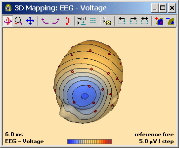
2D (left) and 3D (right) voltage maps in single head view at one time point. The EEG shows a detected event in the Av33 user-defined montage.
The mapping window appears also when a cursor is set in the EEG data display by clicking onto the EEG.
The mapping window can appear in four different layouts: Single map, 6 maps in standard view, 15 serial maps, or customized series of maps. For details on 3D maps see the section "3D Maps".
3D Maps
Introduction
Maps are projected onto a 3D standardized head surface for a more realistic display of voltage topography. The head surface was generated by averaging the MRI images of 24 normal subjects after transformation to the Talairach space using the BrainVoyagerTM software. The standard 10-10 electrodes were adjusted to each individual head using the nasion, pre-auricular points (T9, T10), the inion and the eye canthii as landmarks. Using the spherical spline interpolation over the whole head, reference-free maps are calculated.
Controls
Use the mouse and the keyboard as follows:
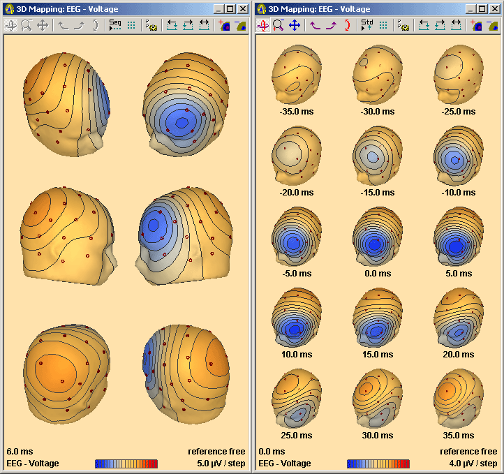
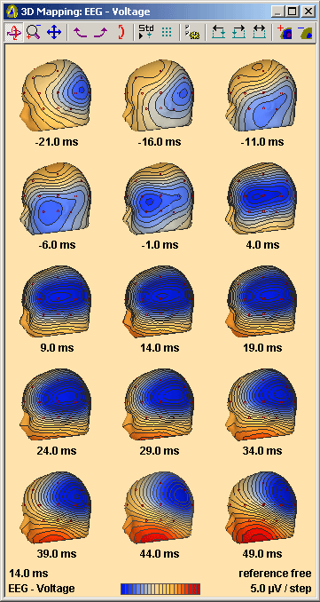
- Click on a map in the standard whole head view with 6 preset viewpoints to display 15 serial maps in the selected view.
- Click on a serial map to select a specific time for the display of the 6 standard whole-head maps.
3D whole head maps at one latency using 6 standard viewpoints (left) and at a sequence of 15 latencies in serial view (right)
- Double-click on a standard or serial map to obtain a single enlarged map.
- Drag over the head to rotate or use standard rotation buttons (for more details see below).
- Click or double click on the single head to obtain the 15 serial maps.
- Click on the EEG-Voltage label (bottom left) to display CSD maps. Click on the EEG-C.S.D. label which appears to redisplay voltage maps,
- or type M or V for voltage maps and C for CSD maps.
- When you move the mouse pointer over an electrode, the electrode label (and voltage if in voltage mode) is displayed.
- Left and right cursor keys plot new maps one time unit before or after the current time point. The time units can be adjusted using the Timing Interval toolbar button.

- Up and down cursor keys raise or lower the scaling units of the map display. 3 steps change the scaling by a factor of 2.
- In the sequential and single map views, the head can be rotated, zoomed, or moved, by clicking and dragging with the mouse, depending on which of the 3D Rotate, 3DMagnify, 3D Move buttons in the toolbar has been depressed (see below). In addition, the three mouse dragging functions can be controlled directly by holding down the Shift, Ctrl, or Ctrl+Shift keys:
- Shift-Drag: Rotate
- Ctrl-Drag: Move
- Shift+Ctrl-Drag: Magnify/Zoom
- Hit the Escape key to close the map window.
Toolbar
The toolbar offers a convenient way to modify the mapping display. The buttons are grouped as follows:
The 3D Rotate, 3D Magnify, and 3D Move buttons select what happens when you click and drag with the mouse on a map:
Maps can be rotated (left button pressed), zoomed (middle button pressed), or moved (right button pressed).
The buttons are only enabled when 3D maps series or single heads are displayed. They are grayed in the standard 6-head view.
The 3D Fast Rotation buttons rotate maps in steps of 45°, to the left (left button pressed), to the right (middle button pressed), or vertically (right button pressed).
The buttons are only enabled when maps series or single heads are displayed. They are grayed in the standard 6-head view.
These buttons control mapping layout and options.
The left button, Seq-Std Display, toggles between the standard 6-head view (6 maps from different viewpoints) and the standard sequential top view display with 15 serial maps.
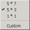
The middle button, Serial Arrangement, opens a dropdown menu that allows for selection of either 5 x 7, 5 x 3 serial maps, a single map (1 x 1), or a custom array of serial maps:
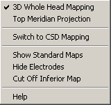
The right button, Options, opens the Options popup menu that allows for general settings of the maps:
- Toggle between 3D or 2D mapping
- Toggle between whole head mapping and top meridian projection
- Toggle between voltage and CSD display
- Toggle between serial and standard maps
- Toggle whether maps cover the entire head or are cut off at the lower part of the head
- Toggle display of electrodes on the maps
- Open the online Help
These buttons control the timing of maps: Pressing the left button, Timing Left, generates maps one time unit earlier than the current map. Pressing the middle button, Timing Right, generates maps one time unit later than the current map. In serial maps, clicking on the Timing Left/Right buttons in the toolbar moves the center latency to the first or last latency displayed, i.e. by 7 intervals in the standard 15 serial view.
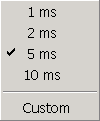
Pressing the right button, Timing Interval, opens a dropdown menu, allowing for the definition of the time interval between sequential maps or the frequency spacing between FFT maps. Voltages and CSD are interpolated to allow for the following standard and custom interval settings:
The final two buttons, Scaling, raise (left) or lower (right) the scaling of the
maps. 3 steps change the scaling by a factor of 2.
Right Click Popup Menu
A right click on the voltage or CSD maps displays the Options popup menu that allows for general settings of the maps:
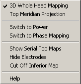
A right click on FFT maps displays the Options popup menu with specific settings for FFT and phase maps:
2D Maps
2D Maps are generated by spherical spline interpolation and are projected onto a spherical head outline. The display shows contour lines. Red contour lines denote positive voltage, whereas blue contour lines stand for negative voltage. In addition, areas of negative voltage are denoted by a dotted pattern.
The user interaction in 2D maps is essentially the same as in 3D maps.
Only the differences are listed here:
-
 In sequential time view, dragging with the left mouse button over the heads rotates them by 90 degrees. The same is achieved using the standard rotation toolbar buttons
- The buttons 3D Rotate, 3D Magnify, 3D Move, are disabled in 2D maps.
A top meridian projection of the heads can be selected either using the options menu (available from the Options toolbar button), or by right click with the mouse onto a map. Top meridian projected maps are cut off at a theta value of 110°.
The 2D maps use equipotential line mapping instead of color maps to avoid bias due to the selection of the color scale and in order to emphasize the shape of the voltage or CSD distribution rather than peak areas. The noise in the EEG tends to produce arbitrary shapes in the maps around zero. Therefore, we have spaced the equipotential lines symmetrically around zero at levels of ±1/2, ±3/2, ±5/2....., and shaded negativities below -1/2 of the scaling between lines. This produces maps that are less biased by EEG noise, especially when larger scales are used. In 3D maps, an additional color shading is shown for each of the potential compartments.
A minimum of 12 scalp channels is required to calculate the spline maps. However, a larger array of electrodes is recommended, including electrodes at inferior lateral sites (see help chapter "Special Topics / Working with Electrodes... / Electrodes / Recommendations for Electrode Placement").
Mapping of the FFT
FFT spectra can be mapped in a similar way as the voltage maps of the ongoing EEG. The maps are initiated from the FFT window (see the chapter "Spectral Analysis / FFT" for more information on FFT analysis).
The results can be shown in three different ways, which are described in detail below:
- FFT maps of amplitude or power showing the topography at a single frequency
- FFT maps of amplitude or power showing the mean over a preset frequency band
- Phase maps showing the voltage amplitude topography at a selected frequency and at a specific or different phase angles. Serial phase maps are encoded to show phase delay (in ms) for better comparison with EEG voltage maps, since phase shift is proportional to time delay. Phase maps are only available if the FFT was computed over a single data block.
The type of map and further mapping options can be selected from the menus Map and Options/Mapping in the FFT window.
Map menu of the FFT window
Note: Mapping of FFT spectra is only possible if there are at least 12 electrodes!
Topographies at a given frequency and at a series of frequencies
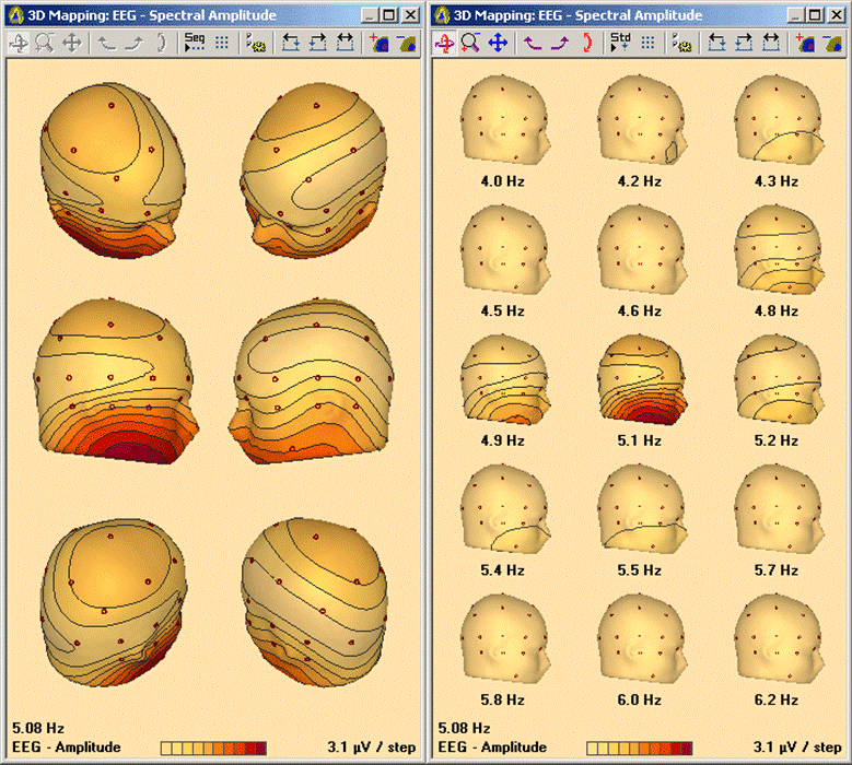
The topography of the amplitude/power at any frequency can be viewed by clicking (single or double click) on an FFT spectral plot at that frequency. As with the voltage/source maps, maps are then plotted on the right of the screen.
3D amplitude maps at a single frequency (left) and at a sequence of frequencies (right)
for one viewing angle
Analogous to voltage maps, clicking on a map will toggle between views from six sides of the head at one frequency (as above left), and a display showing a series of maps at 15 consecutive frequencies in one view (as above right). In the serial view, click on the left/right arrows in the toolbar to page 7 frequencies backward or forward. Pressing the arrow keys on the keyboard pages only one frequency.
The frequency spacing between consecutive maps can be adjusted using the ![]() symbol on the toolbar. Clicking on the Timing Left/Right buttons in the toolbar shifts the consecutive frequency maps analogous to the serial voltage maps.
symbol on the toolbar. Clicking on the Timing Left/Right buttons in the toolbar shifts the consecutive frequency maps analogous to the serial voltage maps.
Topography at the peak frequency
In the FFT window, double click on the peak amplitude or click on the peak frequency value at the right of the FFT spectrum of a prominent channel to view the topography of the peak (dominant) frequency. For bad channels mapping of the peak frequency is disabled.
Topography of a frequency band
To view the topography of the amplitude/ power density within a given frequency band from 6 different views, select the band in the Map menu (for example, to view maps of the theta band, press Alt+M T on the keyboard). To view the topography of the summed amplitude/power over the total frequency range, select the menu item Map/Total. Click on one of the maps to view maps of each frequency band in one head view, together with a map showing the mean over the total frequency range.
If a frequency band is grayed out, its upper or lower limit is out of range for the current FFT. Use the item Band Name and Width in the Options menu of the FFT window to redefine frequency band settings.
Phase maps at a given frequency
Frequency maps visualize the frequency specific distribution of absolute amplitude or power over the scalp. However, these maps do not reveal phase lags caused by multiple underlying processes. Therefore, a series of spherical spline maps (phase maps) is calculated at successive phase angles α, according to
H(f, α) = cos(α) Re(f) + sin(α) Im(f)
where Re(f) and Im(f) are the real and imaginary voltage amplitude topographies at frequency f over the marked block which was transformed by FFT.
A change of topography in consecutive maps indicates multiple underlying processes. Only if there is no change in topography with phase, a single generator process may be assumed. The phase shifts can directly be translated into time lags between the different topographies that are displayed in the phase maps.
To view phase maps at a specific frequency, double click on the FFT signals or click on the peak amplitude value to generate amplitude or power maps at the selected frequency in the standard 6-head view. Then right click onto the map with the best viewpoint to obtain the Options popup menu for FFT maps:
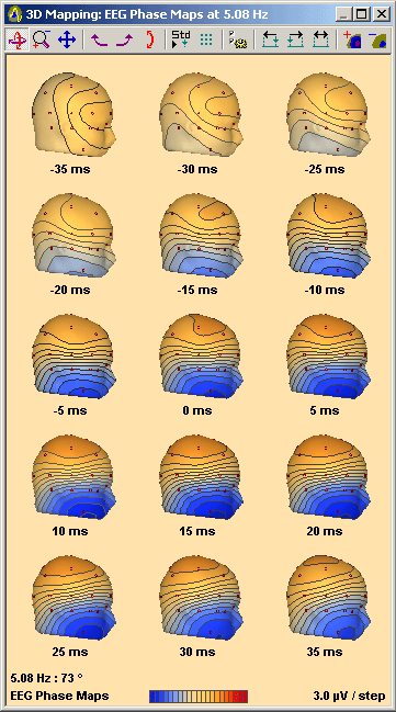
Select Switch to Phase Mapping to obtain a series of 15 serial phase maps in 5 ms intervals. Changes to this interval and other mapping options are described above in section "3D Maps". Clicking on the Timing Left/Right buttons in the toolbar shifts the phase similar to the serial voltage and consecutive frequency maps.
Phase maps can also be initiated from the FFT window using the Map menu.
3D phase maps: This sequence shows a change in topography, indicating that more than one process generates the EEG signals.
Phase maps cannot be generated for mean spectra: generating means over frequencies or over a set of FFTs causes phase information to be lost. Thus, phase maps cannot be shown for frequency bands or for the result of mean FFTs between markers.
Toggling between EEG/MEG FFT maps
For a combined EEG and MEG measurement, the type of map (either EEG or MEG) that is currently selected is displayed in the left upper corner of the FFT window. Initially EEG is displayed. Click on the text to toggle between EEG and MEG FFT maps. A currently open map window will be updated immediately.
Source Images
Source images show the activation of brain regions which are represented by individual channels in source montages (for more information on source montages, see the chapter "Review / Remontaging").
To start a source image, first set a cursor on the pattern of interest by double clicking with the mouse. Use the IMG push button in the control ribbon or hit the 'I' key on the keyboard to display a source image.
When a cursor is set in the waveforms display, you can toggle between voltage maps and source images by pressing or releasing the IMG button. Note that the montage switches automatically to a source montage when the IMG button is pressed. The last active source montage is displayed. If no source montage has been specified for the current EEG data set, the montage TR_Temporal Region is used.
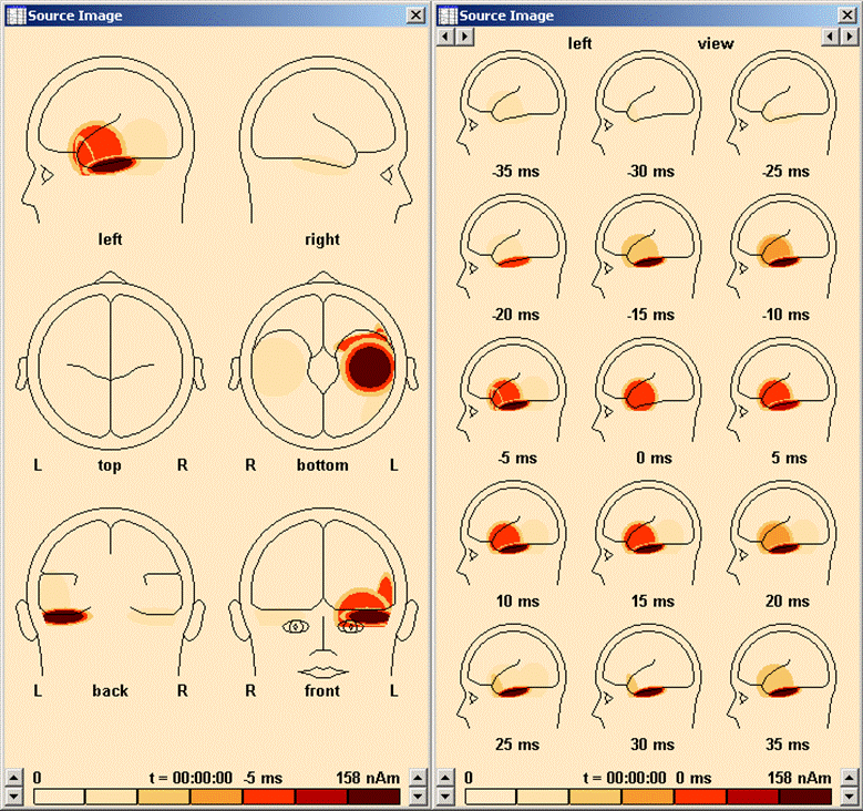
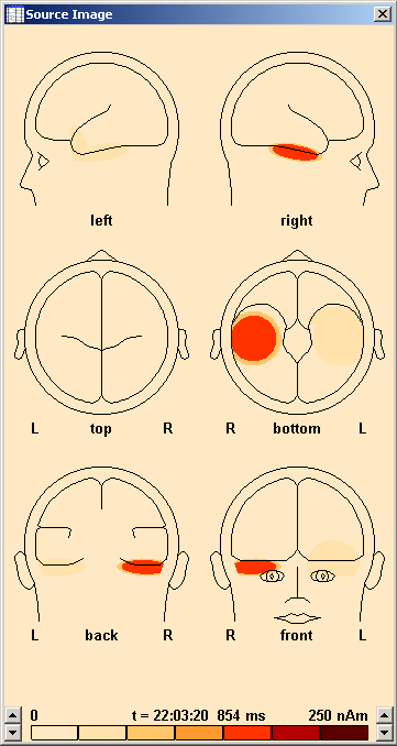
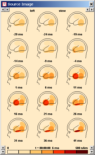
For each dipole channel in the current montage, the activation is shown inside the approximate brain region which is modeled by the dipole source. Regional sources are not included in the image. As in maps, it is possible to toggle between six different views at one latency, and a sequence of 15 images. The activation is shown in 7 shades. The amplitude range is measured in nAm, since the current flow inside the brain is depicted.
Using the arrow buttons at the top, you can change the latency range which is displayed, and the interval between subsequent maps:
- Left group of arrow buttons: These buttons jump 7 maps forward (or backward) in time (i.e. the last (or first) map in the sequence becomes the central map.
- Right group of arrow buttons: These buttons increase (or decrease) the interval between the maps in the sequence
Using the arrow buttons at the bottom, you can adjust the scaling of the source images. They change the amplitude range of the individual shades. The amplitude range between minimum and maximum color is shown at the bottom. In the example below, it is 0 ... 158 nAm.
Images of brain activation during spike propagation in the left temporal lobe from the basal (-20 ms) to the polar (-5 ms) and antero-lateral aspects (0 ms). Each dipole source in the source montage is represented by an ellipsoid which covers the approximate volume modeled by the source. As in maps, different views at the same latency, or a sequence of maps in one view can be shown.
Spherical Spline Maps
Why use spherical spline interpolation?
Spherical spline maps present an interpolation of the potential distribution at the scalp with zero integral over the whole head and maximum smoothness (Pascual et al. 1988; Pernier et al. 1989). Based on these assumptions, the spherical spline method provides an optimal interpolation within the area covered by electrodes on the scalp as well as an optimal extrapolation to the part of the sphere not covered by electrodes. The strength of the spherical spline method stems from the underlying physical boundary
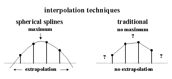
condition: The voltages at the lower part must sum with those at the upper part to zero. Provided that the electrode coordinates are appropriately assigned to equivalent locations on a sphere, maximum smoothness is achieved by the intrinsic properties of splines which can be compared to bending an elastic bar around multiple supporting poles:
Comparison of the effects of spherical splines (left) and linear interpolation (right).
The spherical spline method allows to interpolate and integrate the scalp voltage differences across the entire sphere or whole head. Therefore, it can be used to provide a reference free estimate of the scalp voltages (Rfr-montage), and an estimate of the mean voltage at the ears (Ears-montage). We have compared the spherical spline maps with voltage maps generated by simulated dipole fields due to sources within a multi-shell spherical head model. Even with a small number of scalp electrodes located at the upper half of the head, a very accurate estimate of the reference signal can be obtained. In the worst case of vertical dipole fields (compare example eeg2.eeg) the negative peak at the lower half of the head could be estimated with fair accuracy.
Traditional mapping and source derivations are based on interpolation of the voltages at selected nearby electrodes. This causes problems at electrodes at the boundary of the array and discontinuities within the electrode array. Further, if a voltage maximum lies between electrodes it will not be recognized. In contrast, the spherical spline method provides a maximally smooth interpolation between all electrodes and is capable of extrapolating voltage maxima within and outside of the electrode array. Intrinsically, the spherical splines also provide the optimal estimation of current source density (CSD) which reflects the current flow out of the brain through the skull.
BESA uses an implementation of the spherical splines method as described in the publication 'Spherical splines for scalp potential and current density mapping' by Perrin et al. (Electroencephalogr. Clin. Neurophysiol. 72:184-187, 1989). BESA uses 4th order spherical splines, including Legendre polynomials up to 50th degree. The smoothing constant l can be specified from the menu entry Options / Mapping / Spline Interpolation Smoothing Constant.
Current Source Density (CSD)
What is Current Source Density (CSD)?
The surface Laplacian operator (second spatial derivative of the voltage distribution in tissue) calculates the volume current flow out of the brain through the skull into the skin. That is why we use the term Current Source Density (CSD). The CSD montage will show a large signal if the cortical surface (convexity) is active. This corresponds to a radial superficial dipole.
If the brain activity is in a fissure (tangential dipole) the CSD signal is much weaker. The current flow in a tangential direction, so you will see two peaks of opposite polarity in the CSD maps, corresponding to where the volume current is leaving (+) and entering (-) the skull. The two zones of maximum current are closer together than in voltage maps, because the voltage is an integral over current source density.
Units of current source density are voltage per unit distance per unit distance (e.g. µV/cm²) or current per unit area (e.g. µA/cm²). Conversion from the second derivative of the voltage to current units is a complex issue because this requires knowledge about conductivities of the skull and scalp surfaces. Therefore, µV/cm² is used, i.e. just the second derivative of the voltage distribution.
Mapping/Tutorial
The aim of this section is to generate map and source image displays. It is assumed that you have loaded EEG2 (data: sub-folder Examples\EEG_Focus\eeg2.eeg, electrode file: eeg2.elb, filters variable 1.6-35 Hz, Org montage).
Basic steps
- 1. Move to the periodic pattern in EEG2 by clicking on the event marked at the middle of the event bar.
- 2. Double click on any of the peak deflections to set a mark at the cursor position. A vertical bar (dark red on a yellow background) will be set, and Voltage maps will be displayed automatically. The latency will be shown at the bottom of the map window.
- 3. Repeat double clicking on several different peaks to view the maps at different latencies. Type the Esc key to close the map window.
- 4. Press the SRC button, and from the dropdown menu select the TR-Temporal Region montage. Double-click on one of the peaks to display voltage maps again.
- 5. Press the IMG button, so that it remains down. The map display changes to source images calculated from the magnitude of the source channels at the marked latency.
- 6. Repeat double clicking on several different peaks to view the source images at different latencies. Click on the up/down arrows to the right or left of the scaling bar below the images to increase or decrease scaling.
- 7. Select a prominent peak and double click to display the source images. On the keyboard press the left and right arrows to display source images at the next/previous sampling point or 5 ms later/earlier. Click on the up/down arrows right or left of the scale bar to increase or decrease scaling.
- 8. The latency should still be marked from the previous step. Type M to display voltage maps instead of the source images at the currently marked latency, and type 'i' again if you want to view the source images.
- 9. Press the IMG button again. Source images are switched off and 3D amplitude maps are displayed. Click on a map to convert the display from standard to sequential view.
- 10. Click and drag on a map to rotate the head to a new position. Note how all the maps in the sequential view are redrawn in the new position.
- 11. Try out the various controls on the 3D map toolbar (at the top of the map window. See chapter “3D Maps” for descriptions of the toolbar controls. Finally, switch back to 2D maps by disengaging the 3D button.
- 12. You may also select Voltage maps or any other process from the Process menu when a latency is marked and a source montage is displayed. Note that voltage maps can be displayed in all montages by clicking anywhere on the EEG, if the IMG button is not down.
- 13. Select average reference montage Avr, and repeat double clicking on several different peaks (Note that typing 'i' will change to the last active source montage again and display source images).
- 14. Display voltage maps and make sure that electrodes are shown (if not, right-click on one of the heads, and select Show Electrodes from the popup menu. If selected, the electrode locations, projected on the 6 different views of the head model, will be displayed. Select Top Meridian Projection from the Options/Mapping menu to display a sequence of maps in equidistant steps relative to the marked latency. Note that the sequential maps present top views in meridian projection down to the level of F9, T9, P9, F10, T10, P10. By using spline interpolation, the maps are capable of covering this wider range as compared to traditional maps. Deselect top view sequential maps again.
Map and source image sequences
- 1. Select file segm1.eeg and select the TA_Temporal Lobe source montage. Engage the IMG button. The TA montage includes basal, anterior, and lateral temporal brain regions. Note how this montage suggests the onset of the spike in the left basal temporal lobe, with subsequent components in the anterior tip and lateral surface of the left temporal lobe.
- 2. Double click on the positive (upward-going) peak on the third channel from the top of the screen (left lateral temporal lobe). The source image will be displayed.
- 3. Click on the left lateral head view (top left source image). Note how the cursor changes to a hand over areas where clicks initiate an action. A series of 15 equidistant source images around the cursor latency will be displayed.
- 4. Click on the left/right arrows at the left at the top of the map display to page 7 maps backward or forward.
- 5. Click on the left/right arrow at the right at the top of the map display to decrease or increase the interval between the sequential maps. Alternatively, you may set the interval in Interval between Sequential Maps in the Options/Mapping menu.
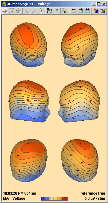
- 6. Type 'm' or 'v' to view a sequence of amplitude maps in the same time range (click the rotate-left button and the rotate-up-down button twice each to arrive at the head positions shown below):
| Review | |
|---|---|
| Source Analysis | |
| Integration with MRI and fMRI | |
| Source Coherence | |
| Export | |
| MATLAB Interface | |
| Special Topics | |

