Difference between revisions of "BESA Research Automatic Artifact Correction"
(Created page with "{{BESAInfobox |title = Module information |module = BESA Research Basic or higher |version = 6.1 or higher }} <!-- == Automatic Artifact Correction == --> Automatic correct...") |
|||
| Line 2: | Line 2: | ||
|title = Module information | |title = Module information | ||
|module = BESA Research Basic or higher | |module = BESA Research Basic or higher | ||
| − | |version = 6.1 or higher | + | |version = BESA Research 6.1 or higher |
}} | }} | ||
| Line 36: | Line 36: | ||
[[Image:Artifact Correction (6).gif]] | [[Image:Artifact Correction (6).gif]] | ||
| − | ''Above, a later segment of the EEG is shown, using the TA_Temporal-Lobe source montage, with and without correction. Note that, without artifact correction, the eye movements are depicted on the channels representing anterior temporal lobe and frontal brain activity. After correction, the artifacts are greatly reduced without distorting the topography of the periodic discharges.'' | + | ''Above, a later segment of the EEG is shown, using the TA_Temporal-Lobe source montage, with and without correction. Note that, without artifact correction, the eye movements are depicted on the channels representing the anterior temporal lobe and frontal brain activity. After correction, the artifacts are greatly reduced without distorting the topography of the periodic discharges.'' |
== Method == | == Method == | ||
| Line 52: | Line 52: | ||
The EOG-HVB source montage contains 3 spatial components to account for eye blinks (B-EOG), as well as vertical (V-EOG) and horizontal eye movements (H-EOG).<br /> | The EOG-HVB source montage contains 3 spatial components to account for eye blinks (B-EOG), as well as vertical (V-EOG) and horizontal eye movements (H-EOG).<br /> | ||
| − | After the transformation, only the temporal activity of the three spatial components for the EOG-HVB source montage | + | After the transformation, only the temporal activity of the three spatial components for the EOG-HVB source montage is used to compute the topographies for the average reference montage in sensor space. For this, the waveforms of the V-EOG and B-EOG dipoles are combined as one component using the following formula: |
:<math display="block">VB – EOG = V – EOG^2 + B – EOG^2</math> | :<math display="block">VB – EOG = V – EOG^2 + B – EOG^2</math> | ||
Latest revision as of 14:21, 5 May 2021
| Module information | |
| Modules | BESA Research Basic or higher |
| Version | BESA Research 6.1 or higher |
Automatic correction is the easiest way to obtain artifact-cleared data for review. The estimation of the correction coefficients can be done using the whole EEG or an epoch defined by markers. If only one marker is set, the EEG is scanned from the beginning to the marker, or from the marker to the end, depending on the current position of the display. The longer the range, the more precisely the topography of the artifact can be defined. However, longer ranges increase computation time.
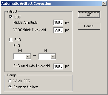
In the Review Window, select the menu entry Artifact / Automatic to bring up the artifact selection dialog box:
By default, EOG correction is computed using an internal model of eye artifact topographies. For automatic EKG correction, an EKG channel has to be defined. If markers are defined (see the figure below), the option Between Markers is ticked automatically.
Clicking OK starts the assignment of the artifact topographies, which can be interrupted at any time using the 'ESC' key on the keyboard.
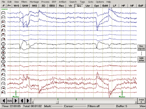
A block of EEG (the example file Examples\EEG-FOCUS\eeg2.eeg) is shown containing eye artifacts. Markers have been placed on either side of the artifacts.
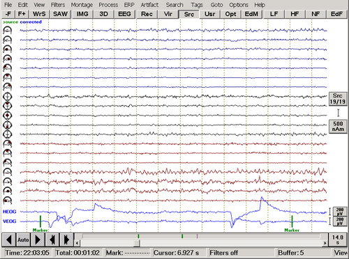
Waveform display after automatic artifact correction. Virtual channels which carry the artifact signal are automatically appended at the bottom.
The corrected waveforms are shown, together with the channels HEOG and VEOG that depict the artifact signals. The oscillatory brain activity is not distorted by artifact correction. Note that correction is applied to scalp channels only. Non-scalp channels, e.g. polygraphic channels, are not corrected and are therefore unaffected by the correction.
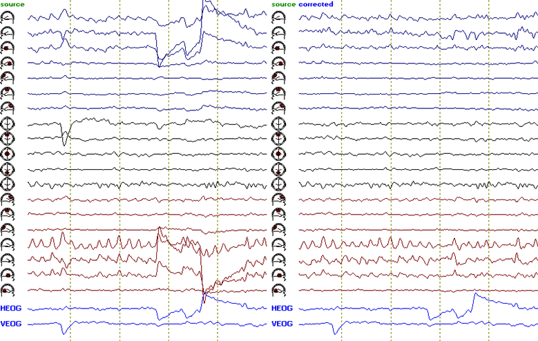
Above, a later segment of the EEG is shown, using the TA_Temporal-Lobe source montage, with and without correction. Note that, without artifact correction, the eye movements are depicted on the channels representing the anterior temporal lobe and frontal brain activity. After correction, the artifacts are greatly reduced without distorting the topography of the periodic discharges.
Method
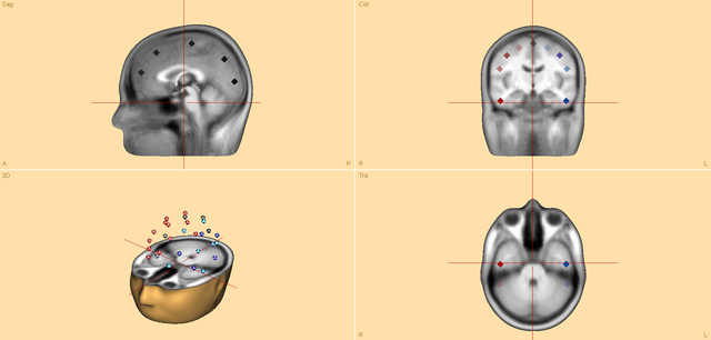
For automatic correction of eye artifacts, sensor data is transformed back into source space using predefined source montages. The BR29 source montage is combined with the EOG-HVB source montage. This provides the advantage of separating brain activity of interest from artifacts.
The BR29 source montage contains 29 (un-oriented) regional sources distributed in the entire brain space.
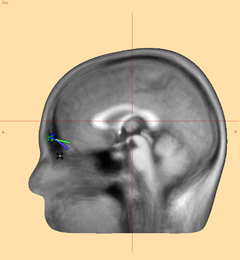
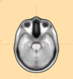
EOG-HVB Source Montage (Sagittal and transversal view)
The EOG-HVB source montage contains 3 spatial components to account for eye blinks (B-EOG), as well as vertical (V-EOG) and horizontal eye movements (H-EOG).
After the transformation, only the temporal activity of the three spatial components for the EOG-HVB source montage is used to compute the topographies for the average reference montage in sensor space. For this, the waveforms of the V-EOG and B-EOG dipoles are combined as one component using the following formula:
- [math]VB – EOG = V – EOG^2 + B – EOG^2[/math]
The H-EOG waveform is not modified. The H-EOG and VB-EOG waveforms are then correlated with the original data to detect EOG artifacts. The corresponding amplitude thresholds can be defined in the Automatic Artifact Correction dialog. In the Review Window, select the menu entry Artifact / Automatic to bring up the dialog box.
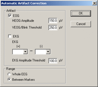
Automatic Artifact Correction Dialog
If the thresholds are exceeded, the current topography will be added to the accumulated topography. Please note that the eye artifact topography will change when scanning for artifacts in the data file and will become more accurate the more eye artifacts are found.
References
- Ille N., Berg P., and Scherg M. A Spatial Components Method for Continuous Artifact Correction in EEG and MEG. Biomed. Tech., 1997, 42 (suppl. 1): 80-83.
- Ille, N., Berg, P., Scherg, M. Artifact correction of the ongoing EEG using spatial filters based on artifact and brain signal topographies. J. Clin. Neurophysiol. 2002, 19: 113-124.
- Uusitalo, M.A., Ilmoniemi, R.J. Signal-space projection method for separating MEG or EEG into components. Med. Biol. Eng. Comput., 1997, 35: 135-140.
| Review | |
|---|---|
| Source Analysis | |
| Integration with MRI and fMRI | |
| Source Coherence | |
| Export | |
| MATLAB Interface | |
| Special Topics | |
