BESA Research Montage Editor
| Module information | |
| Modules | BESA Research Basic or higher |
| Version | 6.1 or higher |
Contents
- 1 Montage Editor - Introduction
- 2 Layout of the Montage Editor
- 3 Creating and Editing a Montage
- 3.1 Creating a New Montage
- 3.2 Editing a Montage
- 3.3 Changing the Reference of Montage Channels
- 3.4 Creating New Average Channel Groups
- 3.5 Changing the Viewing Reference in Referential Montages
- 3.6 Re-reference to Linked Mastoids
- 3.7 Editing a Montage in the 2D View and Pgr/Icr View
- 3.8 Editing a Montage in the Montage Channel List
- 3.9 Editing a Montage in the 3D View
- 4 Loading and Saving Montages
- 5 Standard Montages
- 5.1 Recorded Standard Montages
- 5.2 Virtual Standard Montages
- 5.3 Standard Source Montages
- 5.3.1 Naming Scheme of Standard Sources
- 5.3.2 Source space 25s
- 5.3.3 Standard Source Montage - BR_Brain Regions
- 5.3.4 Standard Source Montage - CR_Central Region
- 5.3.5 Standard Source Montage - FR_Frontal Region
- 5.3.6 Standard Source Montage - PR_Parietal Region
- 5.3.7 Standard Source Montage - TR_Temporal Region
- 5.3.8 Evoked Potentials
- 5.3.9 Standard Source Montage - Resting State Montages
- 5.4 Predefined Additional Channel Montages
Montage Editor - Introduction
The Montage Editor provides information about the current montage and the available standard montages.
The Montage Editor also offers the possibility to create new user-defined montages, modify a standard montage, or combine channels from different montages.
Edited Montages can be saved and selected in the main window of the BESA Research program using the montage push buttons or the montage menu.
The Montage Editor opens after clicking on the EdM push button in the BESA Research control ribbon.
The following chapters will guide you through the most important features and the layout of the Montage Editor.
Layout of the Montage Editor
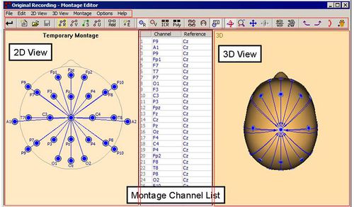
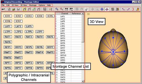
The Montage Editor window is subdivided into three main parts which will be explained briefly in the following sections.
The title bar shows the name of the current montage (the montage which is currently displayed).
Most of the functions and commands can be chosen from the main menu bar and the toolbar below the title bar. However, many commands are also available via a right mouse click. If you right-click, a context-sensitive popup menu may appear containing the available commands.
The functions of the toolbar and the popup menus are described in the next section. A detailed description of the commands of the menu bar is given in electronic help chapter "Montage Editor / Reference".
2D View
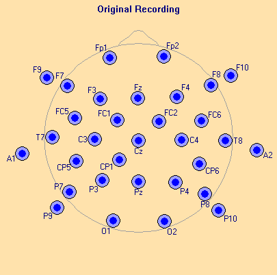
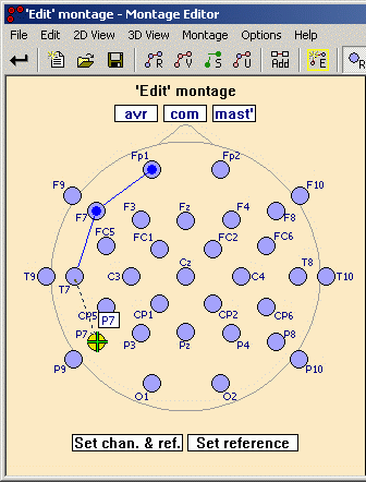
The 2D view displays a scheme of the current montage. Additionally, available electrodes which are not used in the current montage can be shown.
The name of the current montage is given at the top. Note: If the montage name starts with "Add:", an additional channel montage is displayed. Additional channel montages are described in the chapter "Predefined Additional Channel Montages".
![]() Use the One 2D Head toolbar button if you want to switch between the available 2D head views: the top meridian projection, or the top, bottom, back, front, left and right views.
Use the One 2D Head toolbar button if you want to switch between the available 2D head views: the top meridian projection, or the top, bottom, back, front, left and right views.
The top meridian projection shows all electrodes of the current montage. Other 2D head views only show the electrodes which are visible from the corresponding side.
![]() Use the Four 2D Heads toolbar button to switch between the available four head layouts.
Use the Four 2D Heads toolbar button to switch between the available four head layouts.
The following objects are displayed:
![]() Recorded electrodes which are available for the current data file, not interpolated and not marked as 'bad'.
Recorded electrodes which are available for the current data file, not interpolated and not marked as 'bad'.
![]() Interpolated electrodes which have been set as 'to be interpolated' in the main program.
Interpolated electrodes which have been set as 'to be interpolated' in the main program.
![]() Bad electrodes or bad MEG sensors which have been marked as 'bad' in the main program.
Bad electrodes or bad MEG sensors which have been marked as 'bad' in the main program.
![]() Virtual electrodes at predefined locations. The interpolated 81 electrodes are always available for EEG data files.
Virtual electrodes at predefined locations. The interpolated 81 electrodes are always available for EEG data files.
![]() MEG sensors which are available for the current data file.
MEG sensors which are available for the current data file.
![]()
![]()
![]() Montage channels with the underlying recorded/virtual electrode or MEG sensor as primary channel and no reference channel or a reference channel which is not visible for the current 2D head view or which is no single channel reference – may be a reference calculated by several channels, e.g. avr or ears. If a montage channel is selected, the inner circle becomes darker.
Montage channels with the underlying recorded/virtual electrode or MEG sensor as primary channel and no reference channel or a reference channel which is not visible for the current 2D head view or which is no single channel reference – may be a reference calculated by several channels, e.g. avr or ears. If a montage channel is selected, the inner circle becomes darker.
![]()
![]() Montage channels with underlying recorded/virtual electrode as primary channel (left electrode) and the right electrode as reference, connected with the montage channel line. If a montage channel is selected, the blue/red circle and the montage channel line become darker.
Montage channels with underlying recorded/virtual electrode as primary channel (left electrode) and the right electrode as reference, connected with the montage channel line. If a montage channel is selected, the blue/red circle and the montage channel line become darker.
Additional objects are visible if the 'Edit' montage is displayed. The chapter "Montage Editor / Editing a Montage / Editing in the 2D View and Icr/Pgr View" gives a description of these objects and explains how the 'Edit' montage can be modified.
A right mouse click on a montage channel in the 2D view opens a context-sensitive popup menu for fast access to the most important commands.
Montage Channel List
The montage channel list is displayed to the right of the 2D View. It displays all montage channels of the current montage.
A montage channel consists of a (primary) channel and may be a reference channel against which the primary channel data are calculated. In the example shown above (which really does not make much sense but shows most of the available channel types) the recorded electrode Pz and the virtual electrode Cz are used as references.
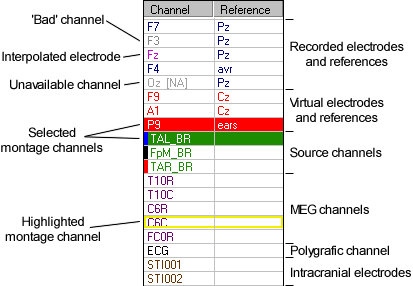
Distinctions are made between channel and reference types and states as follows:
- Recorded electrodes: Recorded electrodes which are available for the current data file are displayed in blue. They may be used as primary and reference channels.
- Recorded references: A combined reference based on the recorded electrodes, e.g. avr. They are also displayed in blue.
- Interpolated electrodes: Interpolated electrodes are recorded electrodes that have been set as 'to be interpolated' in the main program. They are displayed in light purple. Interpolated electrodes may be used as primary and reference channels.
- Bad channels: Recorded channels which have been marked as 'bad' for the current data file are displayed in gray. You may use them as primary or reference channels, but the corresponding data waveform will not be displayed in the main program. However, if you switch to a new data file and the channel is no longer marked as 'bad', the corresponding data waveform will be displayed.
- Unavailable channels: Channels which are not available for the current data file are also displayed in gray and the suffix “[NA]” is appended. You may use them as primary or reference channels but the corresponding data waveform will not be displayed in the main program. However, if you switch to a new data file and the channel becomes available, the corresponding data waveform will be displayed.
- Virtual electrodes: Virtual electrodes at predefined locations. They are always available for any (EEG) data file, displayed in red. They may be used as primary and as reference channels.
- Virtual references: A combined reference based on virtual electrodes, e.g. ears. They are also displayed in red.
- Source montage channels: Source montage channels consist of a single dipole or a regional source as primary channel and cannot have a reference. The source labels are displayed in green. The individual source color is given as a small colored bar to the left.
- MEG channels: Recorded MEG channels which are available for the current data file and which are not marked as 'bad' are displayed in dark purple.
- Polygraphic channels: Available polygraphic channels are written in black.
- Intracranial electrodes: Available intracranial electrodes are given in brown.
- Selected montage channels: Labels of selected montage channels are highlighted with a black background. A montage channel can be selected by a left mouse click on the channel label. Hold down the Control key to select more than one montage channel simultaneously.
- Highlighted montage channel: The highlighted montage channel is marked by a yellow rectangle around its label. A montage channel is highlighted if the mouse cursor moves slowly over its label or over the corresponding plot in the 2D view. Only one montage channel can be highlighted at a time.
A right mouse click somewhere in the montage channel list opens a context-sensitive popup menu for fast access to the most important commands.
The chapter "Editing a Montage in the Montage Channel List" gives an explanation of how to modify the 'Edit' montage in the montage channel list.
3D View
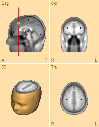
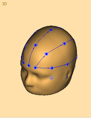
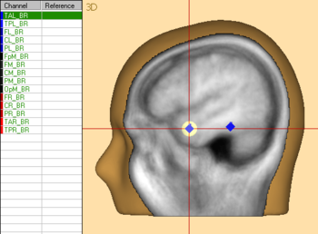
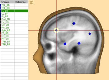
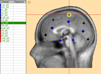
The 3D view is used to visualize the equivalent locations of source channels inside the head in the current montage and to display the recorded EEG channel montage on the 3D head surface.
- If a source montage channel is selected, the 3D view is centered to the source location and the 3D source location is highlighted by a golden halo. If you click on a source in the 3D view, the corresponding montage channel will be selected.
- If scalp electrodes are part of the montage, the 3D whole-head view displays the corresponding electrodes on the head surface.
Editing is not possible in the 3D view. Use the 2D view or the montage channel list instead.
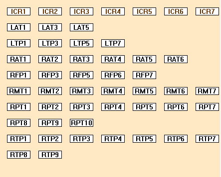
Pgr/Icr View (Polygraphic / Intracranial Channels)
This view displays a scheme of the available polygraphic / intracranial Channels.
![]() Use the Intracranial Channels button to switch on/off the display of intracranial channels.
Use the Intracranial Channels button to switch on/off the display of intracranial channels.
![]() Use the Polygraphic Channels button to switch on/off the display of polygraphic channels.
Use the Polygraphic Channels button to switch on/off the display of polygraphic channels.
The following objects are displayed:
![]() Intracranial electrodes (brown color) which are available for the current data file.
Intracranial electrodes (brown color) which are available for the current data file.
![]() Polygraphic channels (black color) which are available for the current data file.
Polygraphic channels (black color) which are available for the current data file.
Creating and Editing a Montage
Creating a New Montage
![]() Press the New 'Edit' Montage toolbar button.
Press the New 'Edit' Montage toolbar button.
![]() This clears and opens the Edit' montage as indicated by the highlighted ''Edit' Montage toolbar button.
This clears and opens the Edit' montage as indicated by the highlighted ''Edit' Montage toolbar button.
![]() Then select the Recorded Electrodes,
Then select the Recorded Electrodes,
toolbar buttons depending on which type of channels you want to add.
You can add new montage channels now in three different ways:
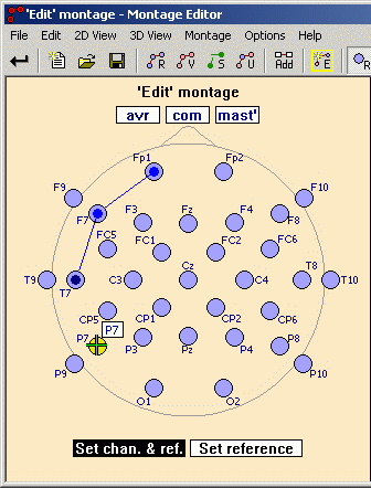
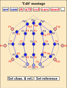
1. Add new montage channels in the 2D view and Pgr/Icr view by selecting channels and dragging to the reference electrode (T7 to P7 in the example below)
2. Click on the Set chan. & ref. text box. This box will start flashing to indicate that new channels can be added. Click alternately on the next channel to be added (in the 2D view, the Pgr/Icr view, or the montage channel list), followed by its reference electrode. Each new click will alternately define a new montage channel and its reference. When done adding new channels, click on the Set chan. & ref. text box again, which will stop flashing.
3. Select one or more channels (see “Editing in the 2D View and Pgr/Icr View” and “Editing in the Montage Channel List”) and add them using the right-click popup menu.
To add source channels, switch to the desired source montage using the Standard Source Montages toolbar button ![]() , select montage channels in the Montage Channel List (see “Editing in the Montage Channel List”), and copy and paste to the 'Edit' Montage.
, select montage channels in the Montage Channel List (see “Editing in the Montage Channel List”), and copy and paste to the 'Edit' Montage.
For more details see the sections “Editing in the 2D View and Pgr/Icr View” and “Editing in the Montage Channel List” below.
Editing a Montage
In the Montage Editor, only one montage can be edited at a time. This is referred to as the 'Edit' montage. The most convenient ways to edit recorded or virtual scalp montages are described below in the sections Editing a Montage in the 2D View and Pgr/Icr View and Editing a Montage in the Montage Channel List
Whenever you want to modify a predefined standard montage, an available user montage, or an additional channel montage, you have to select the montage you want to modify and copy it to the 'Edit' montage. If you have not yet edited a montage after starting the montage editor, the 'Edit' montage is empty.
When you switch from the selected current montage to the 'Edit' montage using the 'Edit' Montage toolbar button ![]() , then the selected current montage is automatically copied to the 'Edit' montage. In addition, the Montage Editor copies the current montage to the 'Edit' montage automatically if you start dragging or deleting montage channels when viewing a selected montage.
, then the selected current montage is automatically copied to the 'Edit' montage. In addition, the Montage Editor copies the current montage to the 'Edit' montage automatically if you start dragging or deleting montage channels when viewing a selected montage.
If the 'Edit' montage is not empty, you can clear it by clicking again on the 'Edit' Montage toolbar button or by clicking on the New 'Edit' Montage button ![]() . Then switch to the montage you want to modify using the Standard User, or Additional Montage buttons and switch back to the 'Edit' montage using the toolbar buttons. This copies the selected montage to the 'Edit' montage.
. Then switch to the montage you want to modify using the Standard User, or Additional Montage buttons and switch back to the 'Edit' montage using the toolbar buttons. This copies the selected montage to the 'Edit' montage.
Changing the Reference of Montage Channels
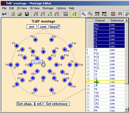
In the 'Edit' montage, select one montage channel by clicking on the related electrode in the 2D View or select the channel from the montage channel list. Select more channels by holding down the Control key.
To change the reference of the selected channels, use the Set Reference text box in one of the following ways:
- Either drag from the Set Reference text box to an electrode in the 2D view, to a channel box in the Pgr/Icr view, to any of the standard reference text boxes at the top of the 2D view (see also Editing a Montage in the 2D View and Pgr/Icr View) or onto a montage channel in the montage channel list as shown below.
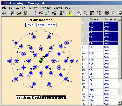
- Or click on the Set Reference text box (it will start flashing), and then click on the desired reference channel in the Montage Channel List, in the 2D view, or in the Pgr/Icr view.
Note: If you want to modify the viewing reference of the recorded Referential or the virtual Referential montage, you don’t have to edit a montage. To change the viewing reference in the referential montages simply switch to the corresponding montage and drag from the Set Reference box to the desired new reference electrode in the 2D view (as shown in the section after next).
Creating New Average Channel Groups
Average channel groups can be used as references in montage channels. They are computed for each time point as the mean voltage over the amplitudes of included channels. If one channel is bad or not available, average channel groups including this channel are also not available.
For the creation of a new average channel group, at least two channels must be selected (see chapter Editing a Montage in the 2D View and Pgr/Icr View for information about how channels are selected). Channels must be of the same type. Source channels and MEG sensors are not allowed in average channel groups.
Channels that have been selected multiple times will enter the average only once.
To create a new average channel group, activate the corresponding menu entry (see chapters “Montage Channel List Popup Menu” and “Edit Menu”).
Note that you can get information about average channel groups which are currently available using the Average Channel Group Information dialog box.
Changing the Viewing Reference in Referential Montages
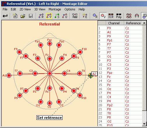
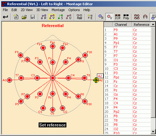
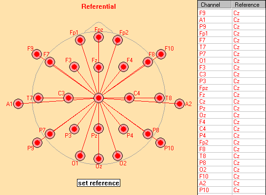
If the recorded Referential or the virtual Referential montage is displayed, an additional Set Reference text box is displayed in the 2D view. In the example below, the viewing reference of the virtual Referential montage is changed from Cz to A2. The Set Reference box can be used to change the viewing reference in one of the following ways:.
- Place the mouse cursor on the Set Reference text box and press and hold the left mouse button. Start to move the mouse while the left mouse button is still held down (“dragging”). The mouse cursor changes to a black cross as soon as dragging has begun. Move the mouse cursor to one of the visible electrodes in the 2D view or to a montage channel in the montage channel list. If the cursor is on top of an electrode or montage channel which can be set as viewing reference, the cross-color changes to green. Release the left mouse button while the cursor cross is green. A new viewing reference is set.
- Alternatively, click on the Set Reference text box. It will start blinking. Then click onto the new reference channel either in the Montage Channel List, in the 2D view, or in the Pgr/Icr view.
Press the Exit and Set toolbar button ![]() to return to the main window of the BESA Research program.
to return to the main window of the BESA Research program.
Re-reference to Linked Mastoids
In case the linked mastoids channels are classified as polygraphic, the following steps can be performed to create a linked mastoids reference montage.
- With the raw data set opened in BESA Research, press File -> Head surface points and sensors -> Save all file in Head Coordinates
- Open the exported *.ela file in a text editor. You will see that all of your electrodes have the label EEG and the mastoids will have the label POL.
- Change the label of the mastoids to EEG.
- Rename the mastoids M1 and M2. The renaming will lead to BESA Research detecting the electrodes as mastoids and giving them standard mastoid positions. Save the file.
- Return to BESA Research and press Ctrl-L. This will open the channel and digitized head surface points dialog. Under Channel configuration browse to the *.ela file that you have just created and load it. You should now see that the mastoids are not displayed in black any longer.
- Press Edit -> Montage. In the middle pane select both your mastoid electrodes M1 and M2 holding down the Ctrl key. Right-click and select Create new channel group. Rename it to Linked Mastoids. The new channel group should appear over the left head scheme. If not, press E on the keyboard. Now select all your channels, press Set reference (bottom left) and click on Linked mastoids.
Editing a Montage in the 2D View and Pgr/Icr View
Reference Boxes
If the 'Edit' montage is displayed, additional reference boxes are displayed at top of the 2D view showing available multiple channel references or average channel groups (see “Create New Average Channel Group”). If not all available reference boxes can be shown, an additional text box ![]() is displayed. If the mouse cursor is positioned over this box, remaining reference boxes will be displayed temporarily. Reference text boxes may be used to define references for new montage channels (see below).
is displayed. If the mouse cursor is positioned over this box, remaining reference boxes will be displayed temporarily. Reference text boxes may be used to define references for new montage channels (see below).
Additional references displayed in blue are recorded references. Additional references shown in red are virtual references. The recorded (virtual) ears reference, for example, is the mean voltage of the amplitudes at recorded (virtual) electrodes A1 and A2. The recorded (virtual) mast reference is the mean voltage of the amplitudes at recorded (virtual) mastoid electrodes M1 and M2. If the electrodes A1/A2 or M1/M2 are not present in the current electrode configuration, or if the electrode locations have been digitized (i.e. the electrodes are not exactly at the default position), a recorded ears or recorded mast reference may be available. This reference is built of the two recorded electrodes that are closest to the standard positions of A1/A2 or M1/M2 if they are within 12 degrees of these standard positions. Note that this assignment of the reference is independent of the actual electrode label in this case. The mast reference in the example below is calculated as mean voltage of the amplitudes at P7 and P8, for example. A recorded ears reference is not available in this example as there are no recorded electrodes within 12 degrees of the standard positions of A1/A2.
Note that you can right-click on a reference box of an average channel group to display the Average Channel Group Information dialog box showing detailed information about available average channel groups.
Selecting Montage Channels
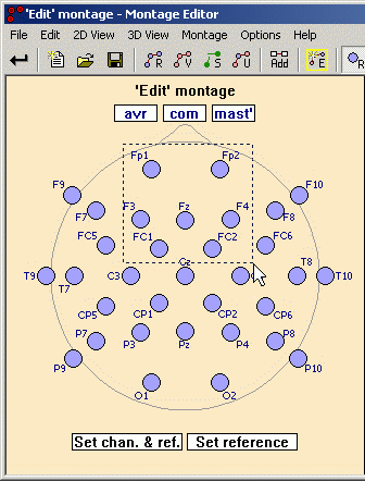
Montage channels can be selected by clicking on the montage channel line or the channel circle/box. If a montage channel is selected, other selected montage channels will be deselected unless you also hold down the Control key. With the Control key, the new montage channel is added to the current selection.
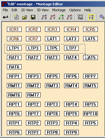
You may also drag a box with the left mouse button to select all channels within the rectangle box. Press the Control key when releasing the mouse button to add the channels to the current selection.
All montage channels are deselected by clicking beneath any montage channel while the Control key is not pressed, or by hitting the Escape key.
Deleting Montage Channels
To delete montage channels, select them and activate the corresponding entry in the Edit menu or in the right-click popup menu, or press the corresponding hot key (default: Delete).
Note: If you want to clear the 'Edit' montage completely, use the corresponding entry in the 'Edit' Montage popup menu.
Adding Montage Channels
There are four ways of adding new montage channels:
- If you previously copied or cut montage channels using the corresponding menu entry in the Edit menu, you can paste them using the same menu or using the associated hot key (default: Control-V). The montage channels are inserted before the first selected montage channel in the 'Edit' montage. If no montage channel is selected, they are appended at the end of the montage channel list.
- Drag from a visible electrode or polygraphic/intracranial channel to another visible electrode or polygraphic/intracranial channel, to one of the additional reference boxes plotted at the top of the 2D view, or to a montage channel in the montage channel list. If the mouse cross becomes green, release the mouse button. The new montage channel will be added at the end of the montage channel list.
toolbar buttons to display or hide the corresponding electrodes/channels.
You can hit the Escape key while dragging if you want to abort the drag operation.
- Click on the Set chan. & ref. text box. This box will start blinking to indicate that new channels can be added. Click alternatively on the next electrode/channel to be added (in the 2D view, The Pgr/Icr view, or the montage channel list), followed by its reference electrode (if required). Each new click will alternatively add a new montage channel and its reference. When done adding new channels, click again on the Set chan. & ref. text box, which will stop blinking.
- Select channels from the 2D view, the Pgr/Icr view, and the montage channel list and right click on a selected channel to display a popup menu, to add the selected channels.
Sorting Montage Channels
In the 2D view or the Pgr/Icr view, there is no way to modify the sequence of montage channels. Use the montage channel list instead as described in the section Editing a Montage in the Montage Channel List.
Changing the Reference
Select the montage channel(s) for which you wish to change the reference. If no montage channel is selected, you can modify the reference for all montage channels simultaneously.
Drag from the Set Reference text box at the bottom of the 2D view to another visible electrode/channel or to one of the additional reference boxes at top of the 2D view. Alternatively, click on the Set Reference text box (it will start blinking), and then click on the desired reference channel in the montage channel list, in the 2D view, or in the Pgr/Inc view.
Note that you can hit the Escape key if you want to abort the drag operation.
Editing a Montage in the Montage Channel List
If the 'Edit' montage is currently displayed, this montage may be modified in the montage channel list as follows:
Selecting Montage Channels
Montage channels can be selected by clicking on the primary channel label box or on the reference label box. If a montage channel is selected, other selected montage channels will be deselected unless you also hold down the Control key. With the Control key pressed, the new montage channel is added to the current selection.
All montage channels are deselected by clicking beneath any montage channel while the Control key is not pressed, or by hitting the Escape key.
Deleting Montage Channels
To delete montage channels, select them and activate the corresponding entry in the Edit menu or in the right click popup menu, or press the corresponding hot key (default: Delete).
Another possibility is to drag them over the left border of the montage channel list – the mouse cursor changes to a litter box icon.
Note: If you want to clear the 'Edit' montage completely, use the corresponding entry in the 'Edit' Montage popup menu.
Adding New Montage Channels
There are two ways to add new montage channels:
- If you previously copied or cut montage channels using the corresponding menu entry in the Edit menu, you can paste them using the same menu or using the associated hot key (default: Control-V). The montage channels are inserted before the first selected montage channel in the 'Edit' montage. If no montage channel is selected, they are appended at the end of the montage channel list.
- Drag the selected montage channels to a position you want to insert them and press the Control key while you release the mouse button. The selected montage channels are copied and inserted at the current mouse position.
Other ways of adding new montage channels are possible in the 2D view or Pgr/Icr view.
Sorting Montage Channels
Drag the selected montage channel(s) with the mouse to the new list position. When releasing the mouse button, the selected montage channels are cut from their current positions and inserted at the new position.
Changing the Reference
Changing the reference of a montage channels is not possible in the montage channel list. Please use the 2D view instead as described in the section Changing the Reference of Montage Channels
Editing a Montage in the 3D View
It is currently not possible to edit a montage in the 3D view. Please use the 2D view and the montage channel list instead and refer to the corresponding chapters.
Loading and Saving Montages
Saving Montages
In the Montage Editor, the 'Edit' montage, user montages, and additional channel montages can be saved. If the 'Edit' montage has been saved using the default settings, it is saved in the User Montages folder and is available from the Usr button (user montages) in the main window of the BESA Reasearch program.
If a montage is saved under a filename which is already used by another montage, the other montage is unloaded. A message box will inform the user before this happens.
If a montage is saved (or loaded) using the same file base name as an existing montage (e.g. Besa Research\Montages\UserMontages\Test.mtg and C:\Temp\Test.mtg), the montage label will receive the appendix “(2)” (Test (2)) etc.
Please note that the file selector dialog box which is displayed if a montage is going to be saved (or loaded) provides an additional selection list at the bottom of the dialog box. The Folders selection list can be used to switch to predefined folders, e.g. the current data file folder, to the User Montages folder or to the Additional Channels folder. The list also shows recently used folders.
By default, the extension .mtg and the User Montages folder is proposed for saving edited montages.
Saving Additional Channel Montages
If you specify the extension .sel when selecting the montage filename, you define that the saved montage belongs to the additional channel montages. Any other extension will result in adding the montage to the user montages after saving. Please make sure that you save additional channel montages either in the standard Additional Channel Montages folder or in the current data folder, if you want to use the montage only for a specific data file.
Note that you can use the filter selection list close to the bottom of the file selector dialog box to switch between “common” montages and additional channel montages.
Loading Montages
To load a montage that is not located in the current data folder or in the User Montages or Additional Channel Montages folders, press the Open Montage push button on the toolbar or use the File / Open Montage menu item. Montages that have already been loaded at program start or by the user can be selected for viewing or editing via the User Montages and Additional Channel Montages toolbar buttons or via the User Montages menu or the Additional Channel Montages menu (please see online help chapter "Montage Editor / Reference / Popup Menus" for detailed information).
If a montage has already been loaded, it is not reloaded unless the file has been modified – e.g. by saving a montage file in the BESA Source Analysis module.
Note that several montages can be selected in the file selector dialog box to be loaded simultaneously.
Automatic Loading of Montages
The Montage Editor loads montages found at default locations automatically:
- At program start, all montages found in the User Montages folder or the Additional Channel Montages folder (and first-level subfolders) are loaded. They are displayed in the first section of the User Montages menu or the Additional Channel Montages menu.
- If the current data file in the main program is switched or a new data file is loaded, all montages</span> found in the new data folder are loaded. They are displayed in the second section of the User Montages menu.
- If a source montage file is stored in the BESA Source Analysis module, it is automatically loaded and displayed in the User montages menu.
Standard Montages
The Montage Editor provides several standard montages which can be applied to all EEG data files. The standard montages are subdivided into three groups:
- Recorded Standard Montages which are based on the recorded electrodes of the current
- Virtual Standard Montages which are based on virtual electrodes at predefined locations, and
- Standard Source Montages which are used to remontage the measured data to show the estimated underlying brain activity.
Additionally, several predefined additional channel montages are available which can be applied to all EEG data files or to data files which contain the corresponding channels, e.g. EKG.
- Predefined Additional Channel Montages are used to display eye activity and EKG or sphenoidal channels below the main montage channels.
See the next sections for details on the different standard montages.
Recorded Standard Montages
Recorded standard montages are sets of predefined channel configurations based on the recorded electrodes of the current data file. In the Montage Editor, recorded standard montages can be selected
using the Recorded Standard Montages popup menu which opens after clicking onto the Recorded Standard Montages toolbar button or activating the corresponding menu entry in the Montage menu.
The Original Recording and Original Average Reference montage have the same sequence of electrodes as the original recorded data. The other recorded standard montages (as well as the virtual standard montages) are derived from predefined montage lists based on a standard set of 27 10-10 electrodes (Std-27):
                      Fp1 Fpz Fp2

                 F9 F7 F3 Fz F4 F8 F10

                A1  T7  C3  Cz  C4  T8  A2

                 P9 P7 P3 Pz P4 P8 P10

                        O1 Oz O2
The Std-27 set includes the 21 electrodes of the 10-20 standard with some traditional labels replaced by the newer 10-10 standard (e.g. T3=T7, T5=P7). If the traditional 10-20 labeling is not set after program installation, it can be restored by entering the following lines in the BESA initialization file BESA.ini under section [Electrodes]:
[Electrodes]

T7=T3

P7=T5

T8=T4

P8=T6
This will relabel the names of these electrodes everywhere in the program. Thus, the standard-27 electrode set will be displayed as:
                      Fp1 Fpz Fp2

                 F9 F7 F3 Fz F4 F8 F10

                A1  T3  C3  Cz  C4  T4  A2

                 P9 T5 P3 Pz P4 T6 P10

                        O1 Oz O2
A predefined montage channel is only displayed in the 2D view, if the recording electrode set contains an electrode that is equal to or close to its location (e.g. A1, T9, TP9 or P9 will be indicated). If the predefined montage channel is bipolar, e.g. A1-Cz, the recording electrode set has to contain electrodes with locations equal or close to the location of both channel (here A1) and reference (here Cz). Otherwise, the montage channel is not displayed in the 2D view. It is grayed in the montage channel list and the suffix “[NA]” is appended (“not available”).
If the common reference used for recording is a known single electrode, the common reference electrode is regarded as part of the recording electrode set. Predefined montage channels using the common reference can be displayed. The common reference will be included in the computation of the average reference. This is not possible, however, for EEG systems using a combination of electrodes as the common reference.
The following recorded standard montages are available:
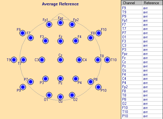
- Average Reference
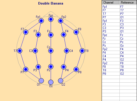
- Double Banana
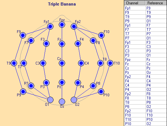
- Triple Banana
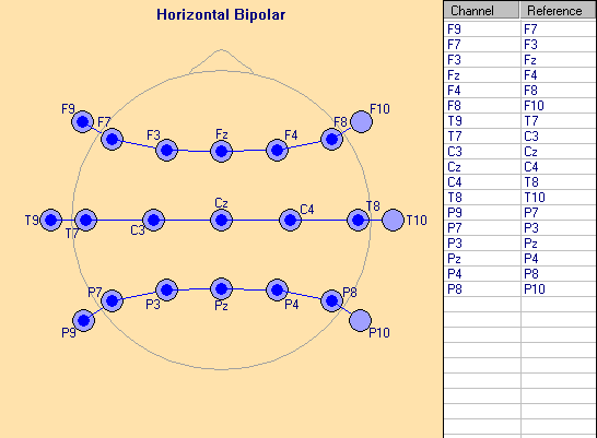
- Horizontal Bipolar
- A1/A2 Reference
- Referential
- Original Recording
- Original Average Reference
Average Reference
In this traditional montage, the available channels of the Std-27 electrode set are displayed against average reference. The average reference is computed for each time point as the mean voltage over the amplitudes of all scalp electrodes that are not bad. If the common reference used for recording is a known single electrode, it will be included in the computation of the average reference.
Double Banana
This is a longitudinal bipolar montage containing two left hemispheric, two right hemispheric and one midline longitudinal row of montage channels. Longitudinal rows are arranged from front to back. Predefined montage channels are only displayed if both channel and reference are available (i.e. recorded and not bad).
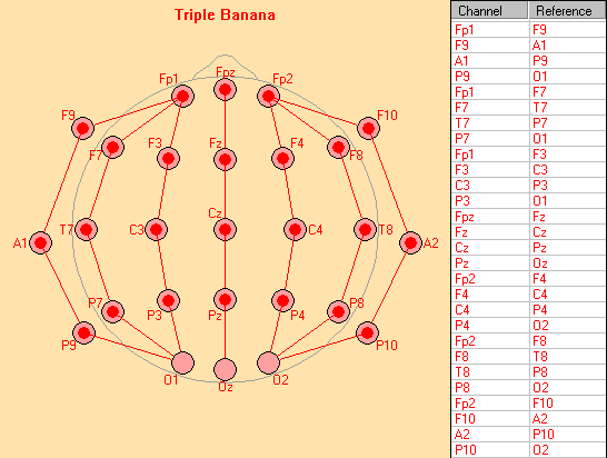
Triple Banana
The Triple Banana montage is an extended longitudinal bipolar montage. It has an additional inferior row on each side as compared to the Double Banana montage. Predefined montage channels are only displayed if both channel and reference are available (i.e. recorded and not bad). The Triple Banana montage is not available if less than 2 inferior electrodes are recorded or defined as ‘good’ on each side.
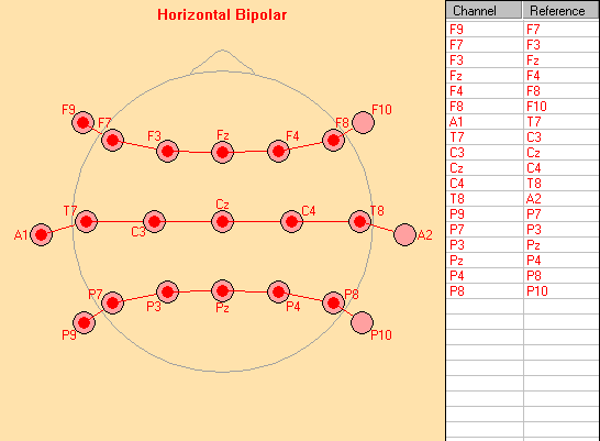
Horizontal Bipolar
The horizontal bipolar montage contains three transversal rows of montage channels. Transversal rows are arranged from left to right. Predefined montage channels are only displayed if both the channel and reference are available (i.e. recorded and not bad).
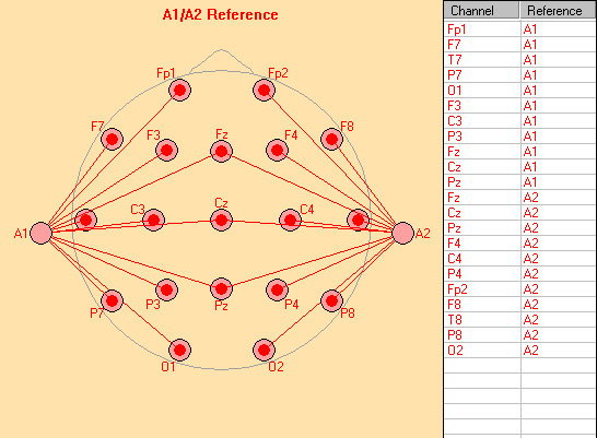
A1/A2 Reference
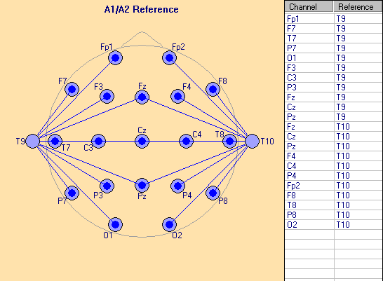
In this traditional montage, the available left-hemispheric channels of the Std-27 electrode set (except inferior electrodes F9, A1, P9) are displayed against the electrode A1 (or, if A1 is not available, a nearby channel such as P9 > T9 > TP9 > M1). The available right-hemispheric channels of the Std-27 electrode set (except inferior electrodes F10, A2, P10) are displayed against the electrode A2 (or a nearby channel such as P10 > T10 > TP10 > M2). The available midline electrodes of the Std-27 electrode set (except Fpz and Oz) are displayed twice, referenced a) to A1 and b) A2 (or a nearby channel). If neither A1 nor A2 nor one of the nearby channels are recorded or defined as ‘good’, the A1/A2 Reference montage is not available.
For this example, the electrodes A1 and A2 are not available. Therefore, the electrodes T9 and T10 have been used instead.
Referential
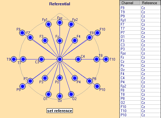
In this traditional montage, the available channels of the Std-27 electrode set are displayed against a common 'viewing reference'. The default viewing reference is Cz. Any of the recording electrodes in the EEG file may be used as viewing reference.
For details on how to change the viewing reference, see chapter Changing the Viewing Reference.
Note that the viewing reference is independent of the common reference used for recording.
Original Recording
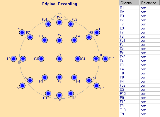
This montage displays the data as recorded. Note that channels defined as 'bad' are displayed in the 2D view and Pgr/Icr view with grey color. In this case, the montage channel label is grayed in the montage channel list.
Original Average Reference
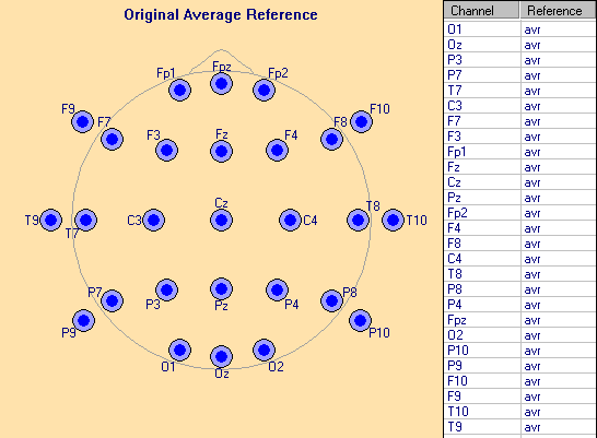
In this montage, the scalp electrodes are displayed in the recording sequence, versus average reference. The average reference is computed for each time point as the mean voltage over the amplitudes of all scalp electrodes that are not bad.
If the common reference is a known single electrode, it will be included in the computation of the average reference.
This montage is not available if the current data file contains no electrodes (e.g. a pure MEG data file).
Virtual Standard Montages
Virtual standard montages are sets of predefined channel configurations based on virtual electrodes. In the Montage Editor, virtual standard montages can be selected using the Virtual Standard Montages popup menu which opens after clicking onto the Virtual Standard Montages toolbar button or activating the corresponding menu entry in the Montage menu.
The virtual montages except Reference Free (10-10) and CSD-Laplacian (10-10) use predefined montage lists based on the same standard set of 27 10-10 electrodes (Std-27) as the recorded standard montages:
                      Fp1 Fpz Fp2

                 F9 F7 F3 Fz F4 F8 F10

                A1  T7  C3  Cz  C4  T8  A2

                 P9 P7 P3 Pz P4 P8 P10

                       O1 Oz O2
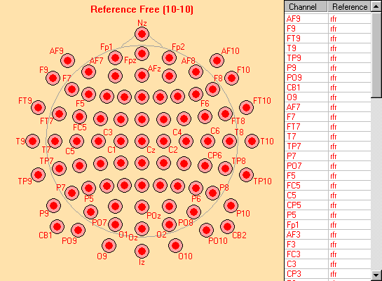
The Std-27 set includes the 21 electrodes of the international 10-20 electrode standard with four traditional labels named according to the newer 10-10 standard (T3=T7, T4=T8, T5=P7, T6=P8). For the standard coordinates of the 27 electrode locations on the sphere see help chapter Recommendations for Electrode Placement. Reference Free (10-10) and CSD-Laplacian (10-10) use predefined montage lists based on a standard set of 81 10-10 electrodes.
Virtual montages estimate the voltage at the idealized locations of the standard 27 (81) electrodes on a sphere using spherical spline interpolation. This method is described in Perrin et al. (Electroenceph. clin. Neurophysiol. 72:184-187, 1989); for more details please refer to chapter “Mapping / Spherical Spline Maps”. Using this interpolation, EEG traces can also be displayed for missing or bad electrodes. The use of interpolation is indicated by the keyword ‘virtual’ displayed in the upper left corner of the waveform window above the montage channel labels. In principal, spherical spline interpolation is possible outside the area covered by the recording electrodes. Over the lower half of the head, interpolation benefits greatly from the presence of inferior lateral electrodes (F9, A1, P9, F10, A2, P10). Although only a minimum of 2 separate channels with lower lateral electrodes is required, for example A1/A2 or M1/M2, the use of 6 or 4 inferior lateral electrodes is recommended.
Note: If the number of scalp electrodes is less than 12, virtual standard montages are not available since spline interpolation and interpolated montages cannot be computed.
The following virtual standard montages are available:
- Reference Free
- 10-10 Average
- CSD-Laplacian
- Double Banana
- Triple Banana
- Horizontal Bipolar
- A1/A2 Reference
- Combined Ears
- Referential
- Reference Free (10-10)
- CSD-Laplacian (10-10)
Virtual Standard Montage - Reference Free
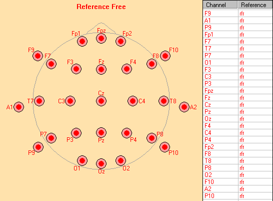
In this montage, the standard 27 interpolated channels are displayed against a reference free average reference. The reference is estimated as the mean voltage over 642 equidistant locations covering the whole head sphere. Voltages are calculated by spherical spline interpolation. According to physics, the voltage integral over the outer surface of the head is zero. By using the mean voltage over the whole head as the reference a close approximation of the true zero reference is obtained.
Virtual Standard Montage - 10-10 Average
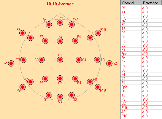
In this montage, the standard 27 interpolated channels are displayed against a virtual average reference. The average reference is computed for each time point as the mean voltage over the interpolated amplitudes of the extended 81 standard virtual scalp electrodes. Since this standard covers inferior electrodes, the 10-10 virtual average reference is not much different from the reference-free montage.
Virtual Standard Montage - CSD-Laplacian
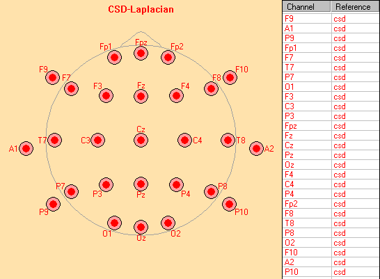
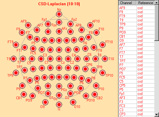
In this montage, current source density (Laplacian) for each of the standard 27 interpolated electrodes is displayed. The CSD waveforms and maps are computed as the second spatial derivative by spherical spline interpolation and are implicitly reference-free. Because this method intrinsically uses information from all electrodes, it provides a more accurate estimation of the source current leaving and entering the skull than source derivations using only 3 or 4 neighboring electrodes. This is particularly true for electrodes at the boundary of the electrode array.
Virtual Standard Montage - Double Banana
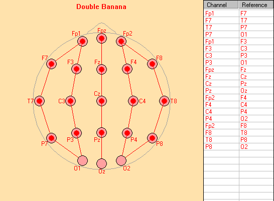
This is a longitudinal bipolar montage containing two left hemispheric, two right hemispheric and one midline longitudinal row of montage channels. Longitudinal rows are arranged from front to back. All channels are interpolated.
Virtual Standard Montage - Triple Banana
The Triple Banana montage is an extended longitudinal bipolar montage. It has an additional inferior row on each side as compared to the Double Banana montage. All channels are interpolated.
Virtual Standard Montage - Horizontal Bipolar
The horizontal bipolar montage contains three transversal rows of montage channels.
Transversal rows are arranged from left to right. All channels are interpolated.
Virtual Standard Montage - A1/A2 Reference
In this montage, the left-hemispheric channels of the standard 27 interpolated channels (except inferior electrodes F9, A1, P9) are displayed against the interpolated voltage at electrode A1. The right-hemispheric channels of the standard 27 interpolated channels (except inferior electrodes F10, A2, P10) are displayed against the interpolated voltage at electrode A2. The midline electrodes of the standard 27 interpolated channels (except Fpz and Oz) are displayed twice, referenced a) to the interpolated voltage at electrode A1 and b) to the interpolated voltage at electrode A2.
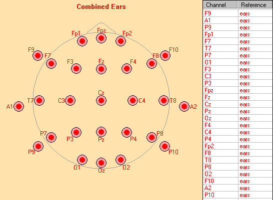
Virtual Standard Montage - Combined Ears
In this montage, the standard 27 interpolated channels are referenced to a computed virtual linked ears reference. The reference is calculated as the mean voltage of the interpolated amplitudes at A1 and A2 determined by spherical spline interpolation. The calculation of the average potential at the ears balances both sides correctly in contrast to the unknown bias when linking the ears or mastoid electrodes directly.
Virtual Standard Montage - Referential
In this montage, the standard 27 interpolated channels are displayed against a common virtual 'viewing reference'. The default viewing reference is Cz virtual. Any of the extended 81 standard virtual electrodes may be used as viewing reference.
For details on how to change the viewing reference, see the help chapter Changing the Viewing Reference.
Virtual Standard Montage - Reference Free (10-10)
In this montage, the extended standard 81 electrode channels are displayed using spherical spline-interpolation and the reference-free mode. The reference is estimated as described for the Reference Free montage. This montage yields more detailed spatial information as compared to the reference free 27 channel montage described above.
Virtual Standard Montage - CSD-Laplacian (10-10)
In this montage, current source density (Laplacian) for each of the standard 81 interpolated electrodes is displayed. The CSD is computed as described for the CSD-Laplacian montage. This montage may yield more spatial information than the 27 channel CSD-Laplacian montage described above.
Standard Source Montages
BESA Research provides several standard brain source montages for EEG review. The majority of these were derived from a set of 15 regional sources covering lateral and midline frontal, central and parietal cortex, midline fronto-polar and occipito-polar cortex as well as anterior and posterior temporal lobes bilaterally. The new source space 25s was derived from 25 sources below the standard 25 electrodes of the IFCN.
The following standard sources montages are provided:
- 25s
- BR_Brain Regions
- FR_Frontal Region
- CR_Central Region
- PR_Parietal Region
- TR_Temporal Region
- Evoked Potentials and MEG
- Resting State Montages
The frontal, central and parietal brain source montages (FR, CR, PR) were derived from the montage BR_Brain Regions in order to emphasize the respective regions in the display. They show the three source activities of each right and left lateral brain region separately along with the 13 other regional sources. The three source activities of each selected region are represented by three single dipoles with radial and tangential orientations. The activities of the right and left dipoles are displayed in the top six source channels of these montages.
The montage focusing onto the temporal lobe have 4 dipoles in each temporal lobe to reveal temporal-basal, polar, antero-lateral and postero-lateral source activities. The basal and polar sources are oriented tangentially, the lateral sources radially. The montage TR_Temporal Region separates these 4 aspects of the temporal lobe against the source currents in the other 11 regions irrespective of their orientation.
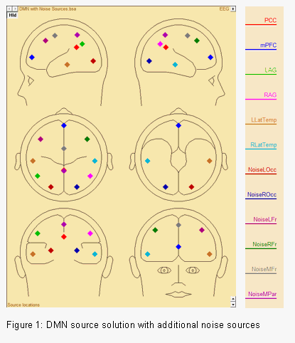
The resting state montages contain regional sources in brain regions associated with the Default Mode Network (DMN), fronto-parietal task control system as well as the dorsal attention system and the ventral attention system. They allow investigating resting state EEG and MEG data in a swift and straight-forward manner. For a more detailed description of the resting state montages, see Resting State Source Montages.
Brain source montages are provided to facilitate the detection of focal source processes in the brain by reversing the overlap from different brain regions seen at the scalp. If brain activity is focal, i.e. represented predominantly in one source waveform, a large amount of the recorded scalp activity reflected in this trace will originate in the related brain region. If source activity is distributed over several traces, the origin is likely to be more widespread or in areas not precisely modeled by the combination of sources in the selected source montage. Each channel in a brain source montage can be viewed as a 'gross virtual electrode' placed onto a particular brain region.
Standardized brain source montages are defined for the 81 standard 10-10 electrodes. Therefore, the recording montage is first interpolated onto the 81 standard electrodes. Then the source waveforms are calculated using the source montage file.
Source montages are labeled using a specific naming scheme to characterize the location, orientation, and type of the underlying source.
Note: If the number of scalp electrodes is less than 12, source montages cannot be computed.
Naming Scheme of Standard Sources
The label of a source channel used in a standard source montage is a combination of the source label itself and the abbreviation of the montage label (separated by an underscore '_').
The source label starts with an abbreviation of the brain region in which the source is located.
The following abbreviations are available:
- C (central),
- F (frontal),
- Fp (fronto-polar),
- Op (occipito-polar),
- P (parietal),
- TA (temporal anterior),
- TB (temporal basal), and
- TP (temporal posterior)
If the source is a single dipole (and no regional source), the dipole orientation is given in the next lower case character. The orientations are specified as follows:
- p (polar),
- r (radial),
- ta (tangential anterior),
- tm (tangential medial),
- tv (tangential vertical), and
- v (vertical).
The last letter before the underscore ('_') which separates the abbreviation of the montage name specifies the hemisphere:
- L (left hemisphere),
- M (midline), and
- R (right hemisphere).
Examples:
- TAL_BR: temporal anterior regional source, left hemisphere, source montage BR_Brain Regions
- FprM_TA: fronto-polar radial single dipole source, midline, source montage TA_Temporal Lobe
Source space 25s
(requires BESA Research 7.0 or higher)
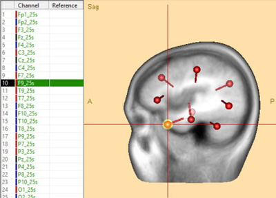
The new source space 25s is based on sources below the standard 25 electrodes of the IFCN (International Federation of Clinical Neurophysiology). The sequence of channels is a reasonable compromise between transversal and longitudinal arrangements while an optimal separation of the major regions, i.e. frontal, central, temporal and parietal-occipital, has been achieved. At the same time, easy hemispheric comparison has been enabled for the frontal and parietal-occipital regions as well as for the left and right temporal channels by grouping these close to each other in the middle of the source space 25s. Thus, when looking at the 25s channels from top to bottom – like onto the head - we are going from frontal to central, include both temporal lobes, and then continue to parietal and occipital.
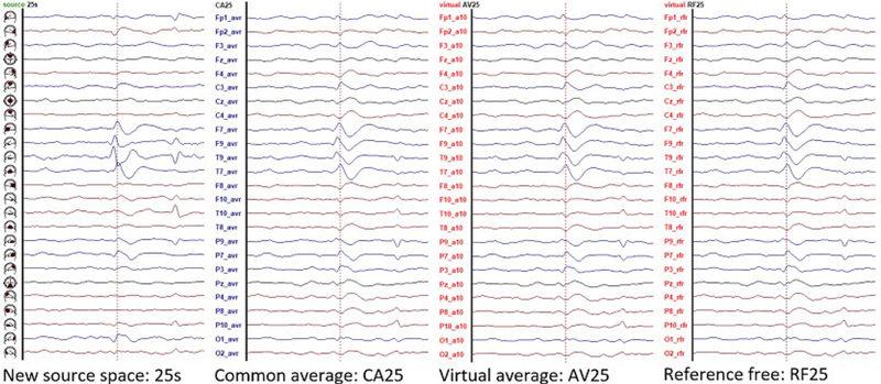
The source channels F9_25s (shown above) and F10_25s have been chosen to reflect mainly temporal polar activity while T9_25s and T10_25s reflect mainly basal activities of the right and left temporal lobes. All other sources reflect primarily the superficial activity of the cortex below each electrode (negative up, dipoles are pointing into cortex). Thus, focal activity (e.g. spikes and some EEG rhythms) can be associated more easily with the regions of origin. Compare focal EEG activity in source space 25s with the montages AV25 (average reference, virtual electrodes), CA25 (common average, recorded electrodes) and RF25 (reference-free, virtual) in folder UserMontages which have a comparable sequence of channels (press Usr for selection).
Below, spike 1 in Examples\Epilepsy\Spikes\SpikeExamples.fsg is displayed. The comparison shows the leading left temporal basal activity most clearly in the new source space 25s:
Standard Source Montage - BR_Brain Regions
This source montage uses a set of 15 regional sources covering lateral and midline frontal, central and parietal cortex, midline fronto-polar and occipito-polar cortex as well as anterior and posterior temporal lobes bilaterally. It separates the activities of the 15 different brain regions and provides for fast comparison and quantification of the different activities.
Note: If the data contains MEG channels, the corresponding MEG montages BRM (for magnetometers and axial gradiometers) and BRG (for planar gradiometers) are located in subfolder MEG.
Standard Source Montage - CR_Central Region
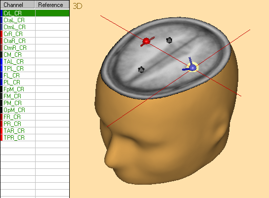
This source montage displays the radial and tangential activities of the central brain region bilaterally in the first 6 single dipole channels. The other 13 regional sources separate the source activities arising from the other brain regions.
Note: If the data contains MEG channels, the corresponding MEG montages BRM (for magnetometers and axial gradiometers) and BRG (for planar gradiometers) are located in subfolder MEG.
Standard Source Montage - FR_Frontal Region
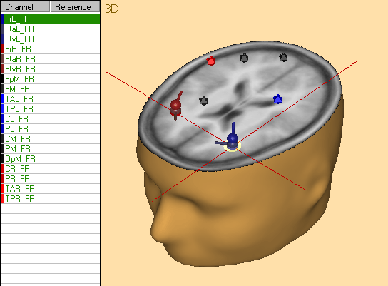
This source montage displays the radial and tangential activities of the frontal brain region bilaterally in the first 6 single dipole channels. The other 13 regional sources separate the source activities arising from the other brain regions.
Note: If the data contains MEG channels, the corresponding MEG montages BRM (for magnetometers and axial gradiometers) and BRG (for planar gradiometers) are located in subfolder MEG.
Standard Source Montage - PR_Parietal Region
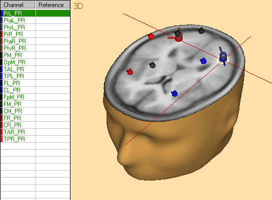
This source montage displays the radial and tangential activities of the parietal brain region bilaterally in the first 6 single dipole channels. The other 13 regional sources separate the source activities arising from the other brain regions.
Note: If the data contains MEG channels, the corresponding MEG montages BRM (for magnetometers and axial gradiometers) and BRG (for planar gradiometers) are located in subfolder MEG.
Standard Source Montage - TR_Temporal Region
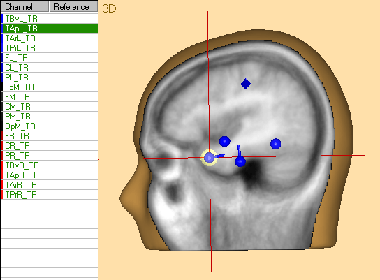
This source montage displays the activities of four different aspects of the temporal lobe bilaterally in the first 8 dipole traces. There are 4 equivalent dipole sources in each temporal lobe to reveal temporal-basal, polar, antero-lateral and postero-lateral source activities. The basal and polar sources are oriented tangentially, the lateral sources radially. The montage TR_Temporal Region separates these 4 aspects of the temporal lobe from the source currents in the other 11 regions irrespective of their orientation. Head schemes illustrate location and orientation of each virtual electrode.
The Temporal Lobe and Temporal Region montages may be used to facilitate the detection of lateralized temporal lobe activities and of the differences of the activities at the various spatial aspects of both temporal lobes. Note that eye movement artifacts may be well represented by the sources at the tip of the temporal lobe due to similarities in the scalp distribution of the related source activities.
Note: If the data contains MEG channels, the corresponding MEG montages BRM (for magnetometers and axial gradiometers) and BRG (for planar gradiometers) are located in subfolder MEG.
Evoked Potentials
BESA Research provides three standard source montages designed specifically for use with auditory (AEP), somatosensory (SEP), and visual (VEP) evoked data. Brain regions that are specifically relevant for the auditory, somatosensory, and visual pathway, respectively, are modeled with equivalent current dipoles. Remaining brain regions are modeled with regional sources. The Evoked Potentials source montages are available for EEG only.
Standard Source Montage - Resting State Montages
Introducing Resting State Networks
The default mode network (DMN) is the most commonly known brain network associated with resting state activity. It comprises brain regions that become less active, when the subject is engaged with a task, and in turn more active when the subject is resting (Raichle, MacLeod et al. 2001; Buckner, Andrews-Hanna et al. 2008). Thinking of the DMN as a “baseline” state of the brain would be misleading, as DMN brain regions have been linked with remembering the past, envisioning future events, and considering the thoughts and perspectives of other people (Buckner, Andrews-Hanna et al. 2008). This internal reflection is likely to happen when the brain is not otherwise engaged and the corresponding network thus becomes active in resting state. Recent research (Power, Cohen et al. 2011; Bressler and Menon 2010) has shown that several other brain networks known to become active during certain tasks can also be identified in resting state. Among them are the fronto-parietal task control system as well as the dorsal and ventral attention system (Power, Cohen et al. 2011). These networks seem to be stable systems that are internally connected even when no particular task is given. The resting state networks DMN, fronto-parietal task control system as well as the dorsal attention system and the ventral attention system are available in BESA Research as source montages. They allow investigating resting state EEG and MEG data in a swift and straight-forward manner.
How the Resting State Source Montages were created
BESA resting state source montages are based on source solutions, for which regional sources were placed at the MNI locations of the brain regions of interest. Source locations were derived from the following publications:
| DMN | Power, Cohen et al. 2011, Supplementary Information |
| Fronto-Parietal Task Control Network | Dosenbah, Fair et al. 2007 |
| Dorsal Attention Network | Power, Cohen et al. 2011, Supplementary Information |
| Ventral Attention Network | Corbetta and Shulman 2002 |
Bilateral Sources representing the same brain regions that were not perfectly symmetrical were symmetrized favoring the position of the less superficial source.
Additional noise sources were placed to increase the sensitivity of the sources of interest. Noise sources are easily identified by their name.
Applying Resting State Source Montages on your data
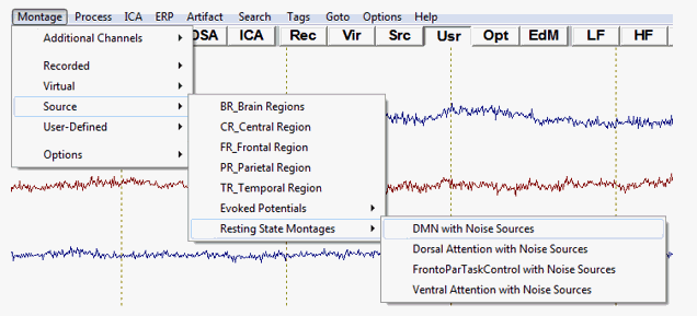
For EEG data, the resting state source solutions were saved as source montages and are automatically available from the Menu "Montage / Source / Resting State Montages". All sources are regularized with a regularization constant of 1%.
For MEG data, source montages are not pre-saved as there are varying MEG sensor types depending on the MEG system and manufacturer. MEG users should send a segment of their raw data to source analysis and load the desired source solution in the source analysis module.
Source solutions for resting state networks can be found here:
“C:\Program Files (x86)\BESA\Research_6_0\Montages\SourceMontages\Resting State Montages”.
After loading the source solution, it is possible to save it as a source montage with File / Save Source Montage As. The source montage will now be applied on the data in the main window and is also available from the menu option Montage / User-Defined.
Mean FFT Analysis in Resting State Source Space
Before applying the desired resting state source montage on the raw data, artifacts should be dealt with either by artifact correction and / or artifact rejection (as part of the mean FFT scan).
After applying the resting state source montage, a mean FFT can be calculated on the source waveforms associated with the source channels, i.e. the ongoing brain activity in the resting state network. Mean FFT performs block-wise FFTs on the whole dataset and the mean output is created when the end of the file is reached. Hereby, information can be drawn on the frequency content of the whole dataset.
Mean FFT can be started from the menu Process / Mean FFT Spectrum. The dialogue allows specifying the data range (by default all data) and the block length, BESA Research will use for calculating individual FFTs. Artifact thresholds for the source channels can also be defined. Mean FFT’s output will give an overview of the frequency content of the individual source channels.
TFC Analysis in Resting State Source Space
For TFC analysis in BESA Research, it is required to insert triggers in the raw resting state data. This can be done by pressing ERP / Insert Triggers. After insertion of the triggers, a paradigm must be created (ERP / Edit Paradigm) that will allow the calculation of the time-frequency plots based on the inserted triggers in the final tab. Please make sure that any filters are only applied for artifact scanning in the filter tab and not for “averaging”, as this would also reduce the frequency domain for time-frequency analysis.
For TFC analysis of resting state data it is recommendable to not use any baseline correction in the paradigm window. If possible, however, a control resting condition should be used (e.g. eyes open / eyes closed) that can be contrasted with the resting state condition of interest in the time-frequency window.
In the time-frequency display, the results should be displayed as absolute values (the ABS button ![]() )
)
If a control condition is available the two resting state conditions can also be contrasted by pressing the according subtraction button (![]() ).
).
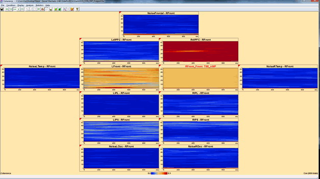
Coherence can be calculated between any resting state source channel and all other channels:
This example shows resting state connectivity between the right-frontal source (red label) and the left-frontal source, as well as the right dorso-lateral prefrontal cortex. No strong coherence is found with the other network sources or the noise sources.
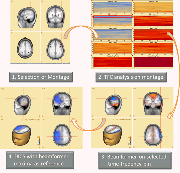
It is possible to apply beamformer and / or DICS analysis on the time-frequency range of interest, suggesting the following possible workflow:
References
- Bressler, S. L. and V. Menon (2010). "Large-scale brain networks in cognition: emerging methods and principles." Trends Cogn Sci 14(6): 277-290.
- Buckner, R. L., J. R. Andrews-Hanna, et al. (2008). "The brain's default network: anatomy, function, and relevance to disease." Ann N Y Acad Sci 1124: 1-38.
- Corbetta, M. and G. L. Shulman (2002). "Control of goal-directed and stimulus-driven attention in the brain." Nat Rev Neurosci 3(3): 201-215.
- Dosenbach, N. U., D. A. Fair, et al. (2007). "Distinct brain networks for adaptive and stable task control in humans." Proc Natl Acad Sci U S A 104(26): 11073-11078.
- Power, J. D., A. L. Cohen, et al. (2011). "Functional network organization of the human brain." Neuron 72(4): 665-678.
- Raichle, M. E., A. M. MacLeod, et al. (2001). "A default mode of brain function." Proc Natl Acad Sci USA 98(2): 676-682.
Predefined Additional Channel Montages
Predefined additional channel montages may be used to display eye activity and EKG or sphenoidal channels in addition to the main montage channels.
In the Montage Editor, additional channel montages can be selected using the Additional Channel Montages popup menu. Open this menu by clicking onto the Additional Channel Montages toolbar button or activate the corresponding entry in the Montage menu.
The following predefined additional channel montages are available:
- EKG
- EOG-HB
- EOG-HV
- EOG-HVB
- EKG+EOG-HB
- EKG+EOG-HV
- EKG+EOG-HVB
- Sphenoidals_Avr
- Sphenoidals_Bip
Additional Channel Montage - EKG
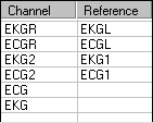
This additional channel montage defines several polygraphic EKG channels. Depending on the recorded channels of your data file, the available EKG channel or channel combination is used.
Note that this montage is not available if the current data file does not contain any EKG channels.
If you use different conventions for defining EKG channels, you may edit this montage in the Montage Editor using copy and paste from the Original Recording montage.
Additional Channel Montage - EOG-HB
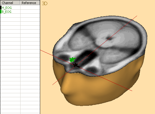
This virtual additional channel montage automatically generates a horizontal EOG channel (H_EOG) and an eye blink channel (B_EOG) from the recorded EEG scalp electrodes using spherical splines interpolation to the standard 81 electrodes and a source montage that contrasts brain and eye activity. It is recommended to reference all electrodes including electrodes near the eyes, e.g. F11, F12, LO1, LO2, IO1, IO2, to the common reference, because this virtual montage can then better separate eye and brain activities (cf. Berg and Scherg, 1994). Special bipolar EOG channels cannot be used in this calculation and are, therefore, not recommended.
The display shows the equivalent centers of the spatial components reflecting the topographies of horizontal eye movements (black) and eye blinks (green).
This automatic virtual montage is currently available for EEG data files only.
Additional Channel Montage - EOG-HV
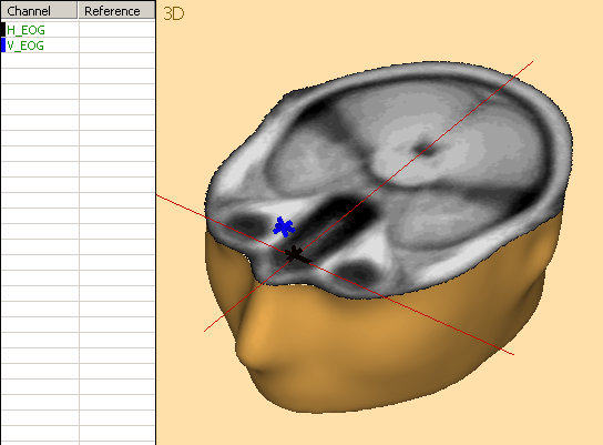
This virtual additional channel montage automatically generates a horizontal (H_EOG) and a vertical (V_EOG) EOG channel from the recorded EEG scalp electrodes using spherical splines interpolation to the standard 81 electrodes and a source montage that contrasts brain and eye activity. It is recommended to reference all electrodes including electrodes near the eyes, e.g. F11, F12, LO1, LO2, IO1, IO2, to the common reference, because this virtual montage can then better separate eye and brain activities (cf. Berg and Scherg, 1994). Special bipolar EOG channels cannot be used in this calculation and are, therefore, not recommended.
The display shows the equivalent centers of the spatial components reflecting the topographies of horizontal (black) and vertical (blue) eye movements.
This automatic virtual montage is currently available for EEG data files only.
Additional Channel Montage - EOG-HVB
This additional channel montage is a combination of the EOG-HB and the EOG-HV additional channel montages. Please see there for a detailed description.
Additional Channel Montage - EKG+EOG-HB
This additional channel montage is a combination of the EKG and the EOG-HB additional channel montages. Please see there for a detailed description.
Additional Channel Montage - EKG+EOG-HV
This additional channel montage is a combination of the EKG and the EOG-HV additional channel montages. Please see there for a detailed description.
Additional Channel Montage - EKG+EOG-HVB
This additional channel montage is a combination of the EKG, the EOG-HB, and the EOG-HV additional channel montages. Please see there for a detailed description.
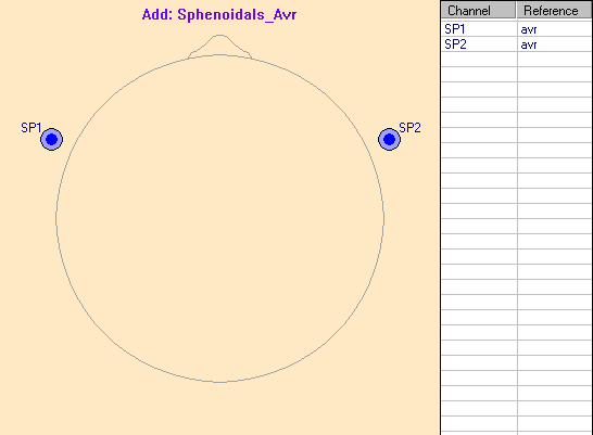
Additional Channel Montage - Sphenoidals_Avr
This additional channel montage allows to display sphenoidal electrodes referenced against the common average reference in parallel with any recorded, virtual, or source montage for comparison.
If the current data file has no channels labeled SP1 and SP2, this montage is not available.
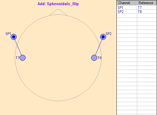
Additional Channel Montage - Sphenoidals_Bip
This additional channel montage allows to display sphenoidal electrodes using a bipolar reference in parallel with any recorded, virtual, or source montage for comparison. The reference is T3/T4 (or T7/T8) to enhance the hemispheric difference of vertical activity resulting from the activation of the inferior surface of the temporal lobe. Note that the standard source montage TR_Temporal Region provides for a better hemispheric separation of right and left temporal lobe activities (see e.g. example EEG-Focus\EEG2.eeg).
If the current data file has no channels labeled SP1 and SP2, this montage is not available.
| Review | |
|---|---|
| Source Analysis | |
| Integration with MRI and fMRI | |
| Source Coherence | |
| Export | |
| MATLAB Interface | |
| Special Topics | |
